Current Differential Relay
GARD 8000 SYS RFL Electronics
June 20, 2014 13-4 973.334.3100
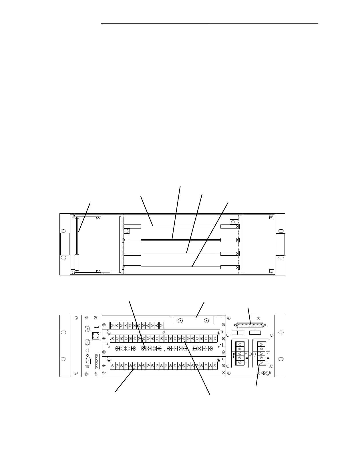
13.2.3 HARDWARE CONFIGURATION
A GARD 8000 System can be built up with Functional Modules as required for a specific application,
with a selectable number of inputs, outputs and communications interfaces. The following overview
describes a factory default configuration of a 3U chassis built up of:
Single Power Supply
Single Main Controller
Display Board with base Teleprotection System
RS 449 communications port on the rear of the PS module (included in Base System)
C37.94 communications module in rear Slot 1
Distance Protection module in front and rear Slot 4
Current Differential Module in Slot 3
6 input module in rear Slot 2
6 output module in rear Slot 2
+
-
+
-
Chassis Front View
Chassis Rear View
Display with TPS (Slot 1)
Distance Relay (Slot 4)
Current Diff (Slot 3)
Single Main Controller (Slot 2)
RS-449
Single Power Supply
C37.94 Comms Module (Slot 1)
Distance Relay (Slot 4)
Current Diff (Slot 3)
6 - Input / 6 - Output Module (Slot 2)
Single Power Supply
Figure 13-2 Front and Rear view of 3U chassis with Current Differential Module (Typical)