Module Descriptions
GARD 8000 SYS RFL Electronics
April 23, 2015 6-35 973.334.3100
6.7.2 SOLID STATE OUTPUT UNIT
The SS Output Unit (500810) has 6 solid state outputs. The contacts are always Form A (normally
opened)
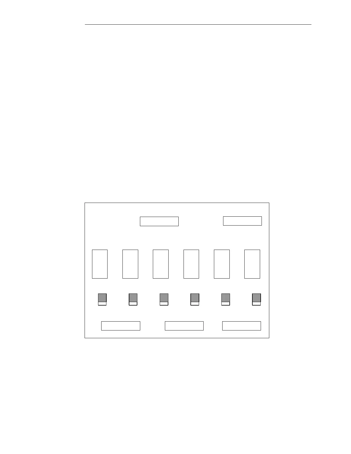
6.7.3 RELAY OUTPUT UNIT
The Relay Output Unit (500815) has 6 relay outputs. The contacts can be Form A (normally opened)
or Form B (normally closed) and can be selected by the user with switches (SW1 through SW6) on the
Relay Output unit. The location of these switches is shown in Figure 6-19.
Form A outputs are selected by moving the switch UP (towards the A) and Form B outputs are selected
by moving the switch DOWN (towards the B). The Relay Output Unit shown in Figure 6-19 has all
switches in the Form A position (normally opened).
When the Relay Output Unit is installed in a Discrete I/O Base module, SW6 on the Relay Output Unit
corresponds to terminals 24 and 23 on the Discrete I/O Base module, SW5 on the Relay Output Unit
corresponds to terminals 22 and 21 on the Discrete I/O Base module, and so forth. The same
correlation exists when the unit is plugged onto a Comms I/O Base module. This is shown pictorially
in Figure 6-20.
SW1
SW2SW3SW4SW5
SW6
K1
K2K3
K4
K5
K6
A
B
GARD 8000 RELAY OUTPUT UNIT
A
AA
B
B
B
B
B
A
A
Figure 6-19. Component side of Relay Output Unit (500815)

 Loading...