Installation and Commissioning
GARD 8000 SYS RFL Electronics
November 28, 2017 4-15 973.334.3100
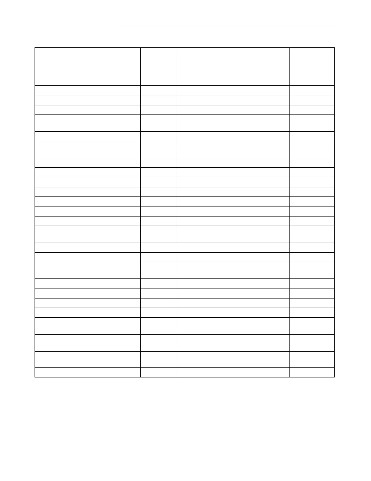
Table 4-3. GARD 8000 modules, general information
Location of Module in GARD 8000
Chassis – Front or Rear
For
Additional
Information
see
Paragraph:
Controller Module (Primary)
Front Slot 2 of 3U Chassis
Front Slot 11 of 6U Chassis
Controller Module (Back-up)
Front Slot 10 of 6U Chassis
Front Slot 1 of 3U Chassis
Front Slot 9 of 6U Chassis
System I/O 6U, E1 Ethernet
System I/O 6U, Fiber Ethernet
System I/O 3U, E1 Ethernet
System I/O 3U, Fiber Ethernet
Mounted on Rear of Front Panel
Piggy Back Mounted on System I/O
Module
Power Line Carrier (Digital Module)
F (Requires 500930 in Rear Slot)
Distance Relay (Set of 2)
One in Front and One in Rear
Metering Module (Set of 2)
One in Front and One in Rear
Telemetry Transmitter Module
Current Differential Relay
Plugs into Discrete I/O Base or Comms I/O
Base
Plugs into Discrete I/O Base or Comms I/O
Base
Plugs into Discrete I/O Base or Comms I/O
Base
Cont…….