Current Differential Relay
GARD 8000 SYS RFL Electronics
June 20, 2014 13-3 973.334.3100
settings. The current differential module in itself is highly programmable but the interaction in the
system has been kept to a minimum in order to simplify the system user interface.
NOTE
While most of the GARD 8000 Modules can be installed and removed while powered, it is not
recommended to do so while Tripping Circuits are enabled as unintended operations may
result.
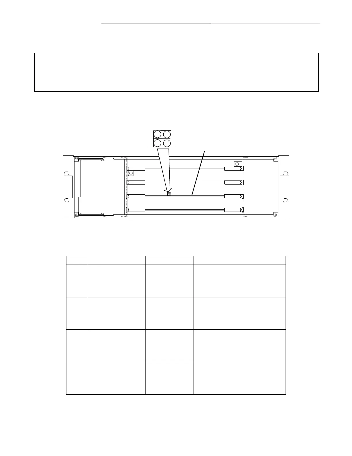
13.2.2 FRONT BOARD LED INDICATION
There are four LED lights located on the front of the board as shown below. Normally these lights are
for RFL diagnostic use only and are accessed by removing the front panel. The LED functions are
listed in the table below.
Chassis Front View
Current Diff (Slot 3)
DS-1
DS-2
DS-3
DS-4
Figure 13-1 Location of Front Panel LEDs
Table 13-1 LED Functions on Front Current Diff. Board
Green
Amber
Blinking Amber
Red
Blinking Red
Comms OK
Backup Mode
No Comms or Backup
Alarm
Un-configured/Disabled
Green
Amber
Blinking Amber
Red
Blinking Red
Comms OK
Backup Mode
No Comms or Backup
Alarm
Un-configured/Disabled
Green
Amber
Blinking Amber
Red
Blinking Red
Comms OK
Backup Mode
No Comms or Backup
Alarm
Un-configured/Disabled
Green
Amber
Blinking Amber
Red
Blinking Red
Comms OK
Backup Mode
No Comms or Backup
Alarm
Un-configured/Disabled
Note: When code is being downloaded all LEDs will blink Amber. When the Relay is burning the flash all LEDs will blink
fast Red. When running the startup BIOS, the LEDs will alternate through Green, Red, Amber, and off.