Installation and Commissioning
GARD 8000 SYS RFL Electronics
November 28, 2017 4-55 973.334.3100
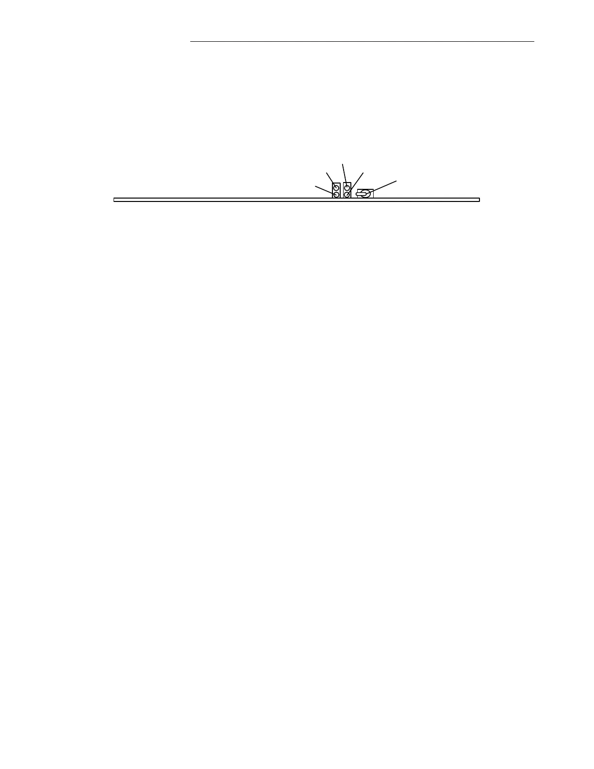
1. A Boot-up progress of the GARD 8000 system can be monitored through the LED #1 located
on the Controller Module (see below). The front panel needs to be removed to observe the
Status LED’s.
2. A complete Boot-up of the GARD 8000 is indicated by the LED #1 lighting Green. For more
information about other status Led’s on the Controller module please refer to the GARD8000
System Manual, section 6.1
DS1
DS2
DS3
DS4
Enable/Disable
Switch
Figure 4-20. GARD 8000 Controller Module (Commissioning, Current Diff)
4.6.4.4 ETHERNET CONNECTION
1. Connect an Ethernet cable from a PC to the front Ethernet port on GARD Display module.
2. Set IP address for a PC to 192.168.1.x (x = 6 to 254)
3. Open the web browser (Internet Explorer version 6 or greater).
4. Enter the GARD front port address into the address bar of the browser (192.168.1.1).
5. Login to the GARD by typing the User Name: Admin and User Password: Admin.
6. Set the rear port IP address (if desired) under ‘Settings’> ‘Chassis Configuration’ > ‘Controller’
page and set the system time through the ‘Systems Labels and Time’ web page.
4.6.4.5 LOGIC/SOFTWARE VERIFICATION
1. At ‘Home’ page click on “Help” and select ‘About’.
2. Verify current Logic and Systems Software revisions.
3. Confirm the programmed Logic file with the Logic name provided in the Reference Control
Drawings.
4. Get familiar with the design of the Current Diff Relay Logic Scheme. The logic inside the
Current Diff Block on the Logic Schematic is fixed as delivered from the factory, but can be
custom ordered for a specific application.
4.6.4.6 CURRENT DIFF RELAY WIRING VERIFICATION
1. Verify the Voltage and Current connections on the Current Diff Relay Input/Output module.
The I/O terminals for the Current Diff Relay are labeled for each Phase and Ground. The I/O
connections are fixed, and should be wired according to the AC schematic shown on the
following page. The Current Diff I/O module (rear interface) must be installed in the
same physical slot as the Current Diff Relay Module (front module).