Power Line Carrier
GARD 8000 SYS RFL Electronics
April 23, 2015 10-34 973.334.3100
10.8.12 MODULE PLACEMENT IN THE RF CHASSIS (100W SYSTEMS)
100 Watt systems will comprise of a 50 Watt system in a 3U high chassis, and will have an additional
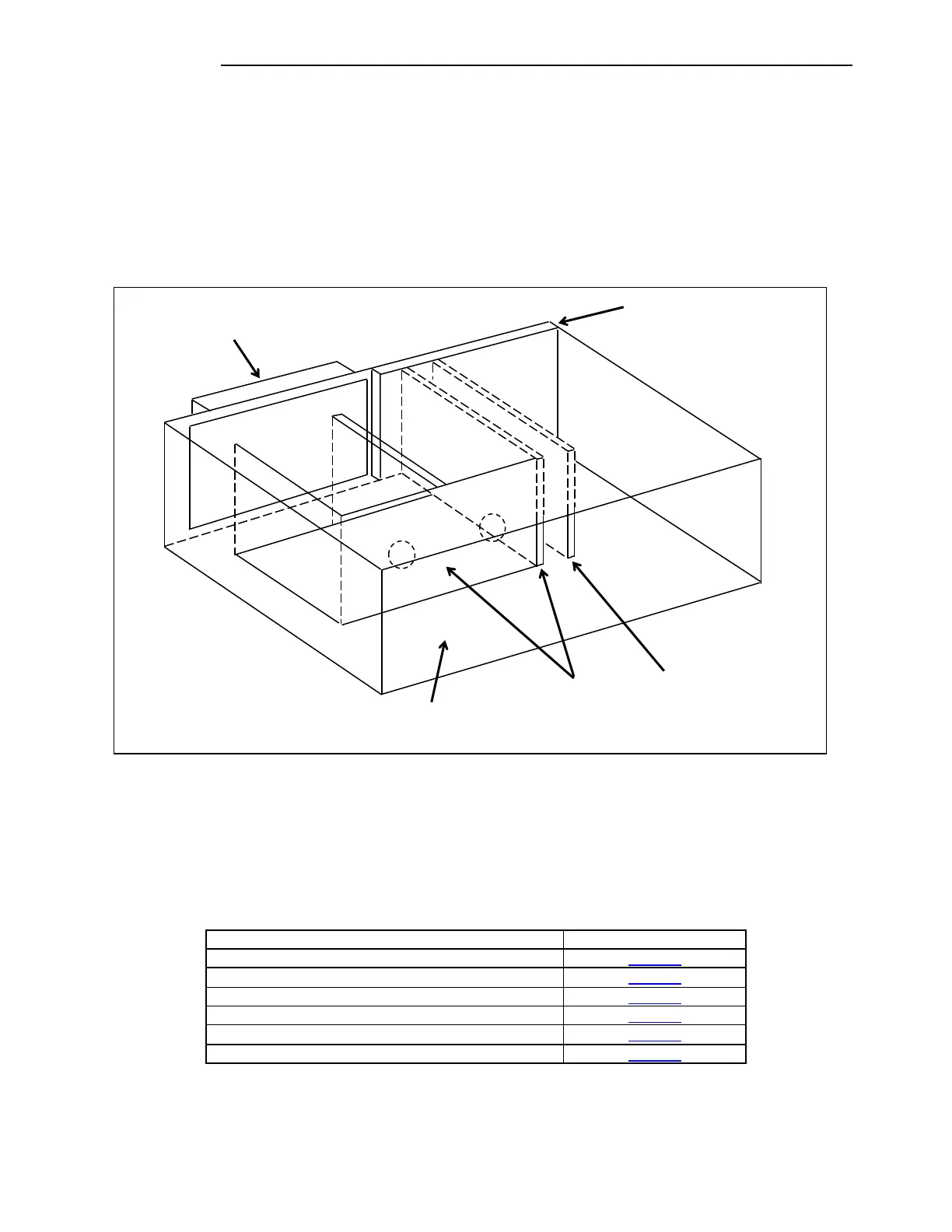
50 Watt unit in a 3U high chassis mounted above it as shown in Figure 10-7. There must be a
minimum 1U space between the lower 3U chassis and the upper 3U chassis for convection cooling.
The top 3U chassis will contain a 50W Power Amplifier, a Power Amp Power Supply, a Tx Filter, an
External Amp Connection Board and a Motherboard. The External Amp Connection Board has no
components and consists only of a PC board and a motherboard connector. A view of the additional 3U
chassis is shown below.
Figure 10-24. Module Placement in the Auxiliary 3U Chassis for the 100W System
10.8.13 SETTING JUMPERS AND SWITCHES IN THE 9508 RF CHASSIS
The Analog Chassis has several modules, which have jumpers or switches that must be set, and
adjustments that must be made, to configure the RFL 9508 system for proper operation. These modules
are listed below.
Table 10-15. RF Analog Chassis Jumper Configurations and other Settings
AMP
BOARD
(Mounted on Front Door,