Power Line Carrier
GARD 8000 SYS RFL Electronics
April 23, 2015 10-42 973.334.3100
10.8.13.4 SETTING JUMPERS AND CONTROLS ON THE LINE BOARD
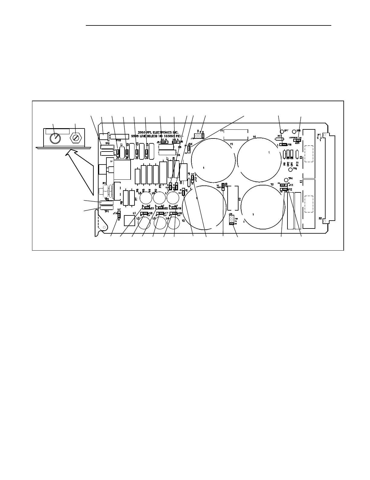
The Line Board has 25 jumpers that must be set for proper system operation. Two of these jumpers,
J10 and J20, are for impedance matching, 12 jumpers are used for balancing the line impedance, and 4
jumpers are used to select 2W or 4W operation. The location of these jumpers is shown below. Refer
to Table 10-17 for information on how to configure these jumpers on the Line Board.
S
1
R1
100
P
200
P
300
P
410
P
.001U
F
.002U
F
12.1 1/
2W
12
2.5W
12
2.5W
50
2.5W
50
5W
.003U
F
.0041U
F
.01U
F
56UH
9.5
A
100UH
9.5
A
180UH
9.5
A
12.1 1/
2W
12.1 1/
2W
8-
18UH
10UH
9.5
A
18UH
9.5
A
33UH
9.5
A
55869
55869
55689
55688
FUSE 2A
250V
FUSEHOLDE
R
32882
FUSEHOLDE
R
32882
FUSE 2A
250V
12
1
47.
5
4733A
4733A
43.
2
ARRESTO
R
92627
99134
180U
H
92627
ARRESTO
R
PART
NUMBER
SERIAL
NUMBER
130/
150
130/
150
G
TP8
J1 J2 J3 J4 J5 J6 J7
J8
J9
J10
J11J12
J16
J25
J20J28J13
J23
J19J14 J21 J15 J22 J17 J18
R1S1
R10TP3
TP1
TP2
Figure 10-30. Location of jumpers on the Line Board