Module Descriptions
GARD 8000 SYS RFL Electronics
April 23, 2015 6-43 973.334.3100
6.9.3 POWER SUPPLY I/O MODULE
38-150/200-300 VDC
3 AMPS 220 W MAX.
!
C
NC
NO
C
NC
NO
RS-499
X.21 V.35
POWER SUPPLY 1
POWER SUPPLY 2
MAJOR
MINOR
SW1 SW2
1 0
1 0
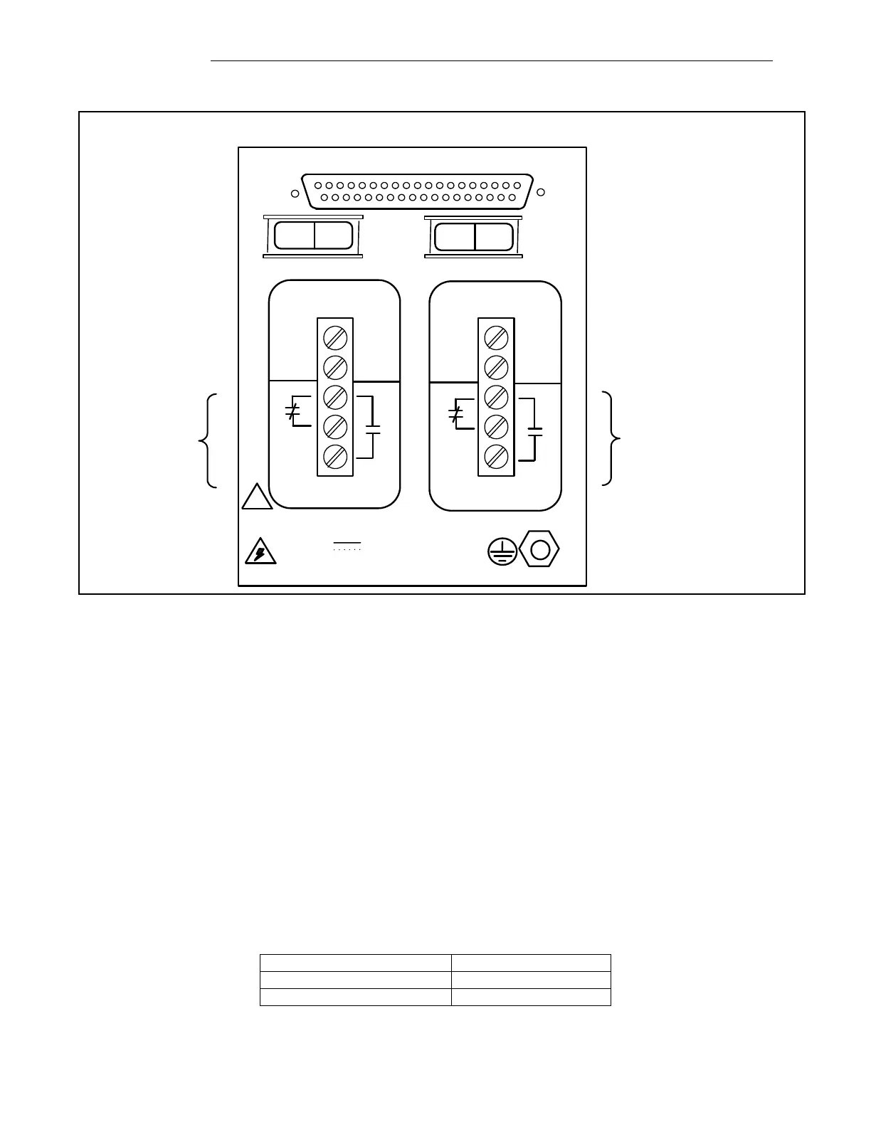
Figure 6-23. Power Supply I/O module, rear panel view
The Power Supply I/O module has the following three major functions:
Connects the internal power supplies to the external power source(s)
Provides major and minor alarm relay contacts
Provides access to the digital interface (RS-449 / X.21 / V.35)
The “+” and “-”designations on the Power Supply I/O module rear panel terminals are totally arbitrary
and the AC or “+” and “-”DC external power sources can be connected to either terminal. The major
and minor alarm relays are contained on this interface and the connections are brought out to the lower
three terminals of each terminal block as shown in the figure above. Both relays are energized under
normal operating conditions and are de-energized for an alarm or alert condition. This ensures that the
chassis will cause an alarm condition when power is lost.
The Power Supply I/O module also has a 37-pin connector for the RS-449 / X.21 / V.35 interface that
is standard with each system. Refer to Tables 4-1 and 4-2 for pin out information.
Table 6-20. Power Supply I/O Module, Multiprotocol assemblies