Tests and Diagnostics
GARD 8000 SYS RFL Electronics
February 14, 2011 11-1 973.334.3100
SECTION 11. TESTS AND DIAGNOSTICS
11.1 INTRODUCTION
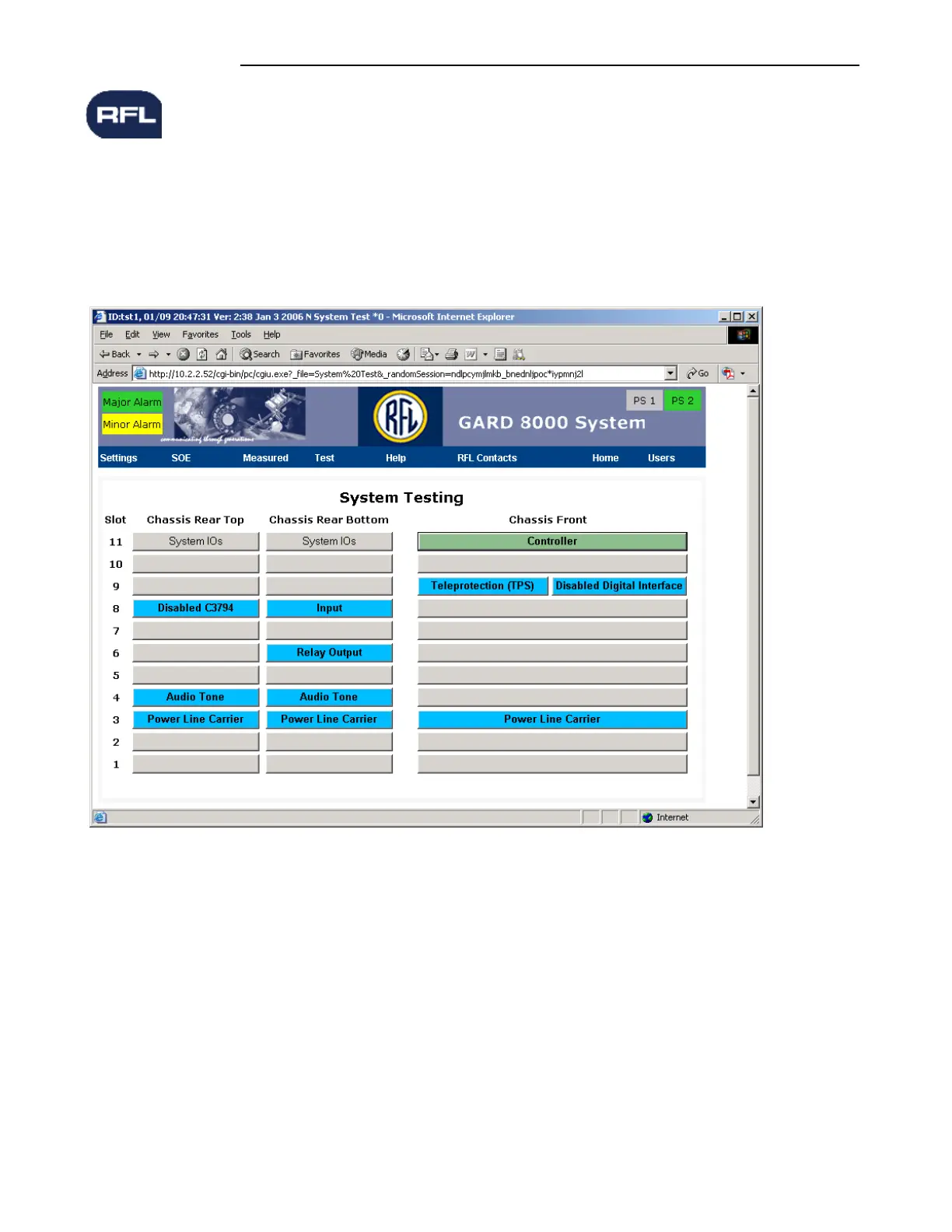
Pointing to Test on the GARD 8000 toolbar and clicking on SYSTEM TEST brings the user to the
System Testing web page. The page consists of a Chassis inventory page with radio buttons for each
functional module. See the Figure below for an example of the 6 rack unit chassis.
Figure 11-1. System Testing web page
In Figure 11-1, the background colors of the card slot locations will change according to the module
status as follows:
Yellow = Alert condition
Green = Normal condition
Blue =Module not configured / Disabled
Red = Alarm condition
Gray =Empty slot