Installation and Commissioning
GARD 8000 SYS RFL Electronics
November 28, 2017 4-9 973.334.3100
Table 4-2. Comms modules mating connectors
J2 = 15-pin female, and BNC
9-pin D-sub 9 female (one per channel)
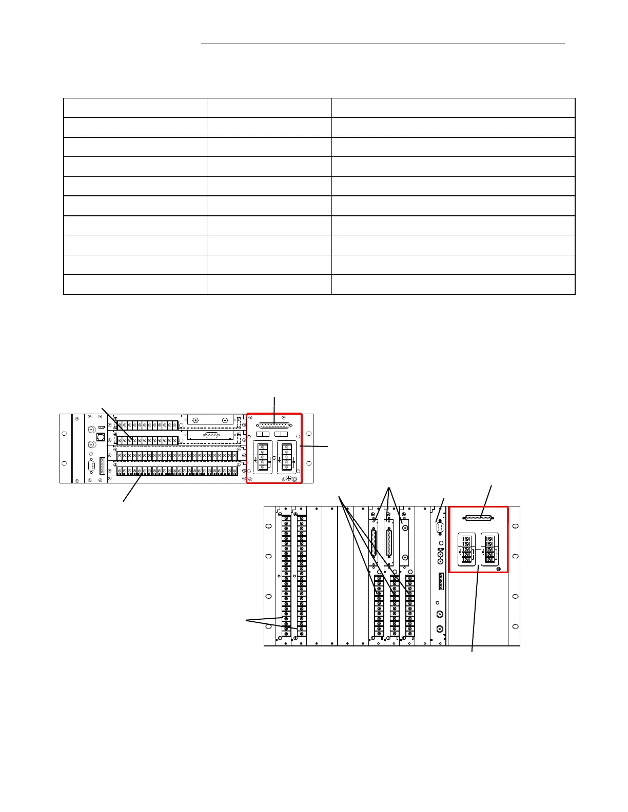
4.5.7.1 MULTI-PROTOCOL CONNECTIONS (RS-449, X.21, V.35)
The illustration below shows the location of the built in communication module on the 3 and 6U
chassis. The following page gives the pin-outs for this connector in both DCE and DTE mode.
Output Module (Slot 4)
+
-
+
-
Input Module (Slot 2)
3U Chassis Rear View
Comms (Built In)
Power Supply I/O
MAJO
R
-
+
S1
2
MINO
R
-
+
S1
3
50085
5
RS-449
X.2
1
V.3
5
24
22
23
20
21
18
19
3
14
16
17
15
13
11
12
9
10
7
8
5
6
4
2
1
24
22
23
20
21
18
19
3
14
16
17
15
13
11
12
9
10
7
8
5
6
4
2
1
V.3
5
X.2
1
RS-449
1PPS
IRIG-
B
GPS
ETHERNET
5
RS-485
MOD BUS
DNP
6
2
3
1
4
SYSTEM I/O
RS-232
500420
50085
5
V.3
5
X.2
1
RS-449
24
23
22
21
17
19
20
18
16
15
14
13
24
23
22
21
17
19
20
18
16
15
14
13
24
23
22
21
17
19
20
18
16
15
14
13
POWER SUPPLY
1
POWER SUPPLY
2
500875
TX
R
X
C37.94
System I/O (Slot 11)
Analog Input (Slot 1 and 2 typical)
6U Chassis Rear View
Additional Comms
(Typical)
Input/Output
Comms (Built In)
Power Supply I/O
Figure 4-4. Location of Synchronous multi-protocol interface