Applications
GARD 8000 SYS RFL Electronics
May 1, 2013 2-14 973.334.3100
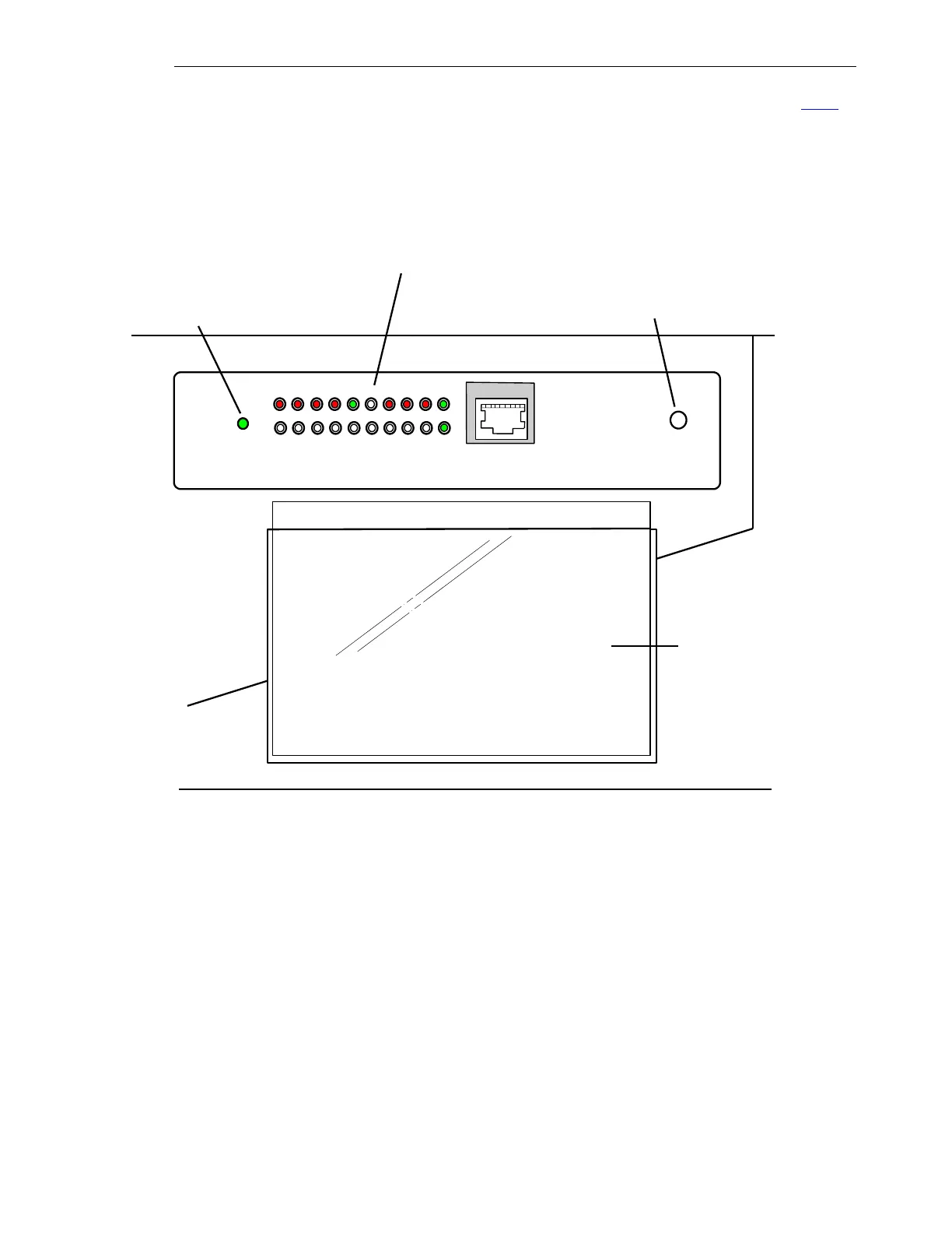
the LED indicators are used; the layout for a 6U chassis is shown on the following page. See 7.3.2
for LED Logic Assignments through the web page interface.
RESET
NETPWR
1
2
20
19
Green indicates that power is
applied to the GARD
Programmable reset button will
reset the LED's as specified
LED assignments are
printed on a card and
inserted into a clear
plastic pocket attached to
the Front Panel
1. LED1
3. LED3
5. LED5
7. LED7
9. LED9
11. LED11
13. LED13
15. LED15
17. LED17
19. LED19 System Major Alarm
2. LED2 Trip Key 1
4. LED4 Trip Key 2
6. LED6 Trip RX 1
8. LED8 Trip RX 2
10. LED10 Guard RX
12. LED12
14. LED14 RX Alarm
16. LED16 TX Fail
18. LED18 RPM Alarm
20. LED20 System Minor Alarm
Each LED can have four color
states: Off, Green, Yellow and Red.
See Fig. 2-11
LED,s are shown active
Figure 2-9. Programmable LED’s, 3U Chassis