System Logic
GARD 8000 SYS RFL Electronics
March 26, 2008 8-5 973.334.3100
8.2.7 LATCH
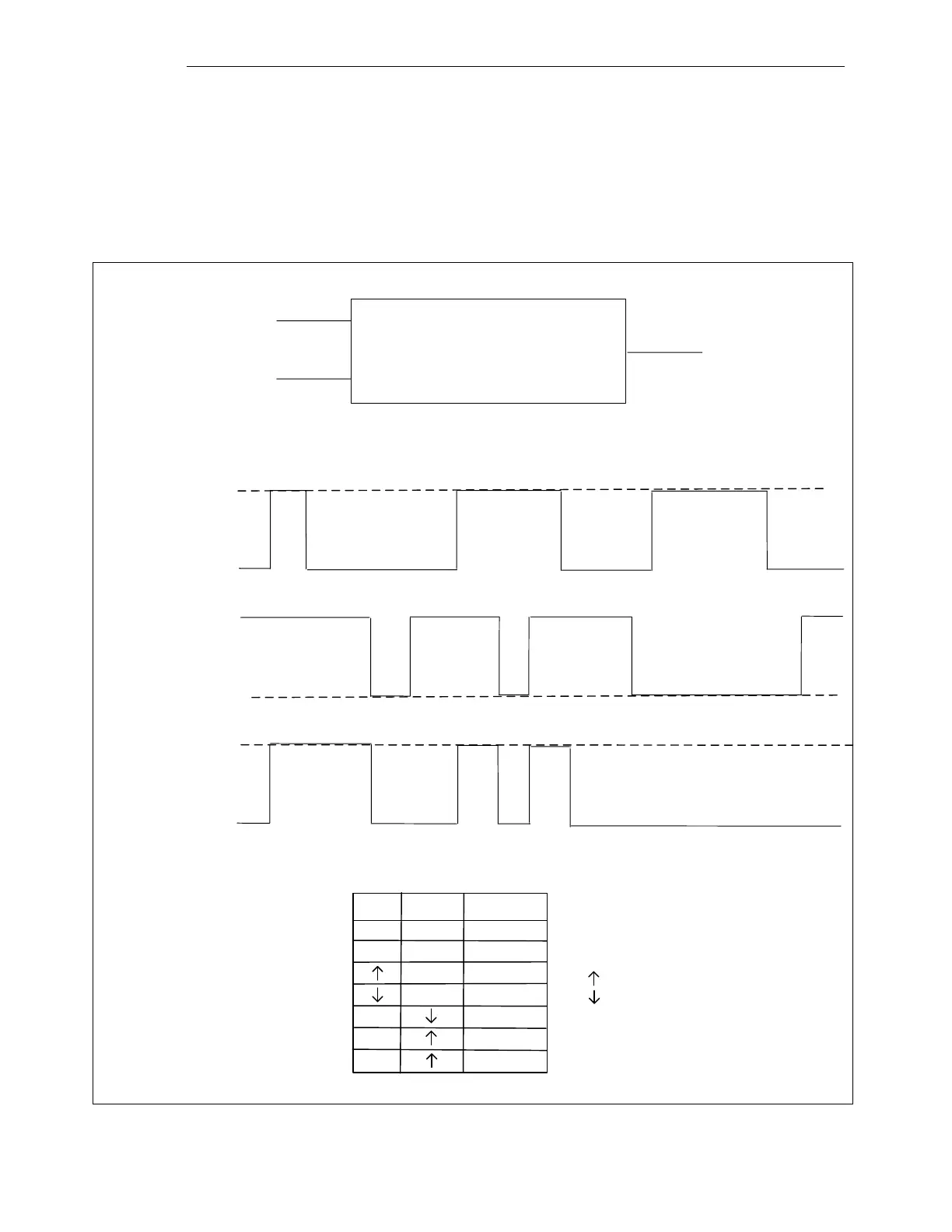
A latch has two inputs and one output, as shown in Figure 8-7. One input is called "SET," and the other
is "RESET”. The SET input is active true and the RESET input is active false. The latch starts out in a
false state. If the RESET input goes false, the output goes false. If the SET input goes true, the output
goes true and stays true unless the RESET is false.
INPUT 1
INPUT 2
SET
RESET
GATE #
OUTPUTQ
TRUE
FALSE
TRUE
FALSE
TRUE
FALSE
a. Symbol
b. Timing Diagram
INPUT 1
(SET)
INPUT 2
(RESET)
OUTPUT
(Q)
Set Reset Output
X
X
L
L
H H
No change
H
H
H
H
No change
L
L
L
H
H = High or True
L = Low or False
= False to True Transition
= True to False Transition
X = Don’t Care
Figure 8-7. Latch