System User Interface
GARD 8000 SYS RFL Electronics
August 1, 2012 5-18 973.334.3100
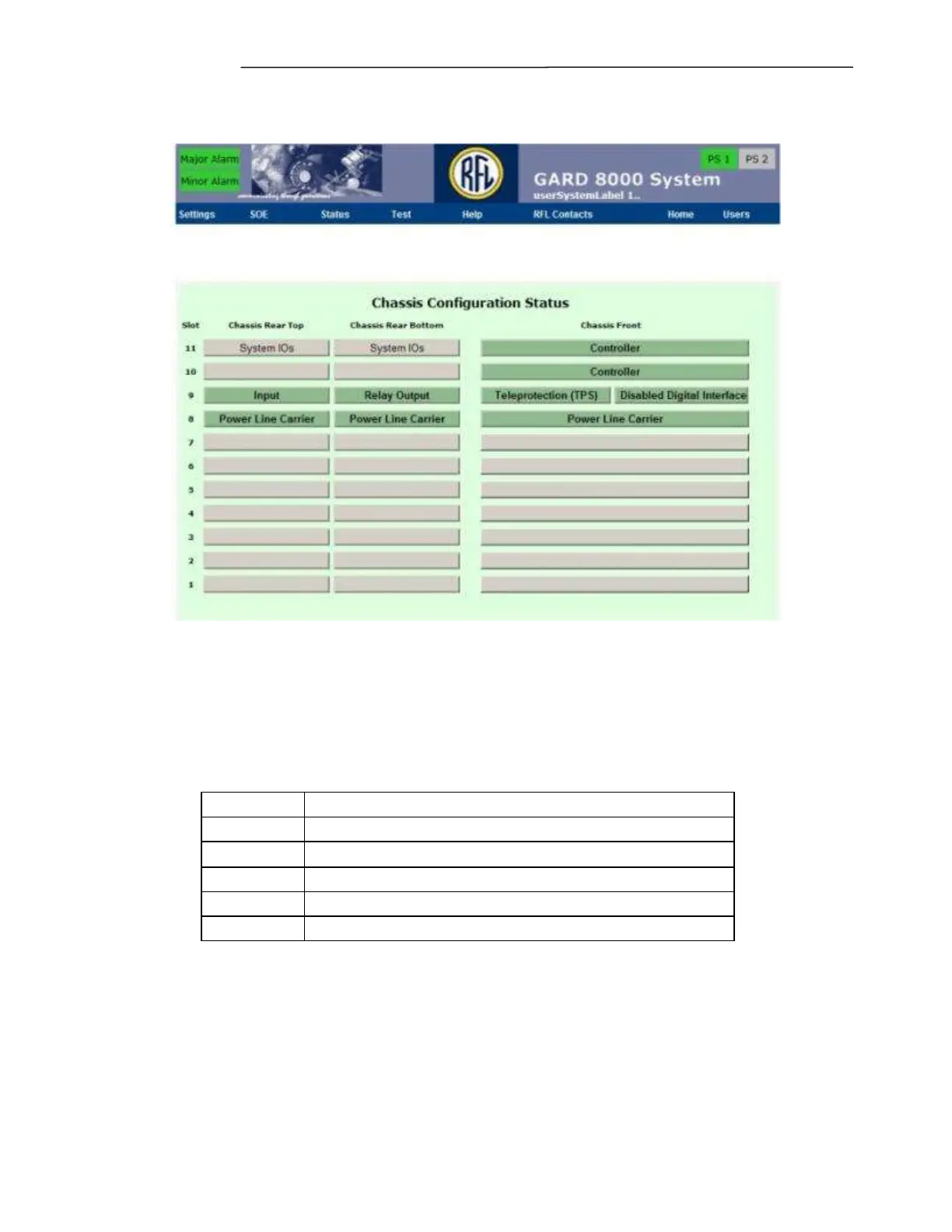
Figure 5-11. Typical Chassis Configuration Status page for 6U chassis.
5.3.1 CHASSIS CONFIGURATION STATUS PAGE GENERAL
INFORMATION
The boxes in the card slot locations can have one of five different background colors. Each background
color represents a different status condition as shown below.
Module not configured or disabled
Once in the ‘Chassis Configuration’ mode Each of the installed modules can be configured, by clicking
on a box. Selecting a module will bring up that modules configuration settings screen.
Refer to the GARD 8000 Distance Relay Manual for information on configuring web pages for the
Distance Relay Module.