Chassis Configuration Settings
GARD 8000 SYS RFL Electronics
April 1, 2012 7-75 973.334.3100
Telemetry Transmitter Module Definitions:
Module Enable/Disable
Toggle switch used to enable the Telemetry Module.
CH1 – 8: Gain
Adjusts the analog gain applied to the input of the channel. The gain is automatically taken into
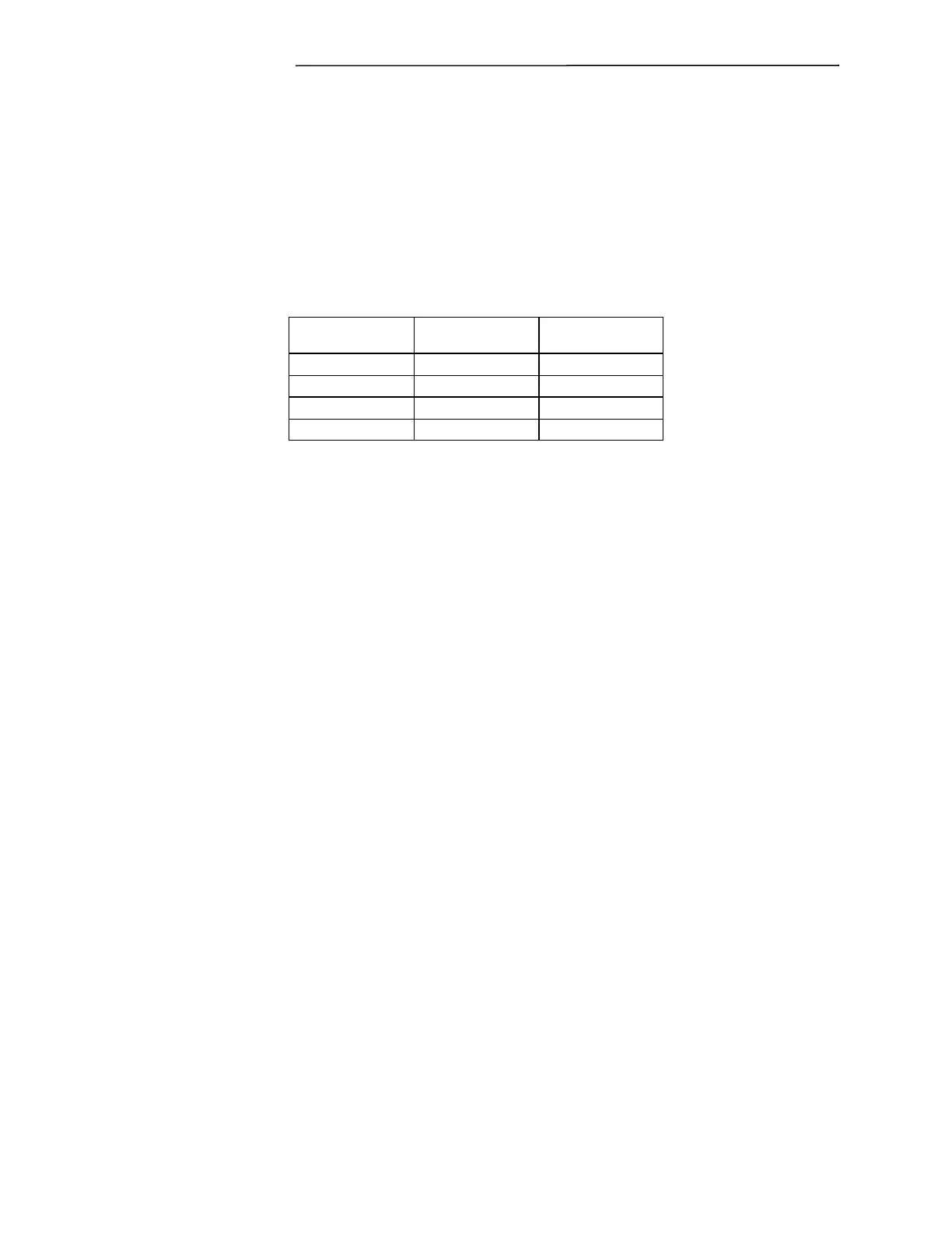
account; the user does not need to divide by the gain. Use the table below to select the ideal gain.
Table 7-5. Telemetry Analog Gain
Calibrate Input
Applies Calibrate Input to the designated channel. Can be used for calibrating off-sets on external
equipment.
Ground Input
Applies GND Input to the designated channel.
A Telemetry Transmitter Status web page can be viewed:
From the home page select Telemetry > General Status. The following web page will appear.


 To Next Page