System Logic
GARD 8000 SYS RFL Electronics
March 26, 2008 8-18 973.334.3100
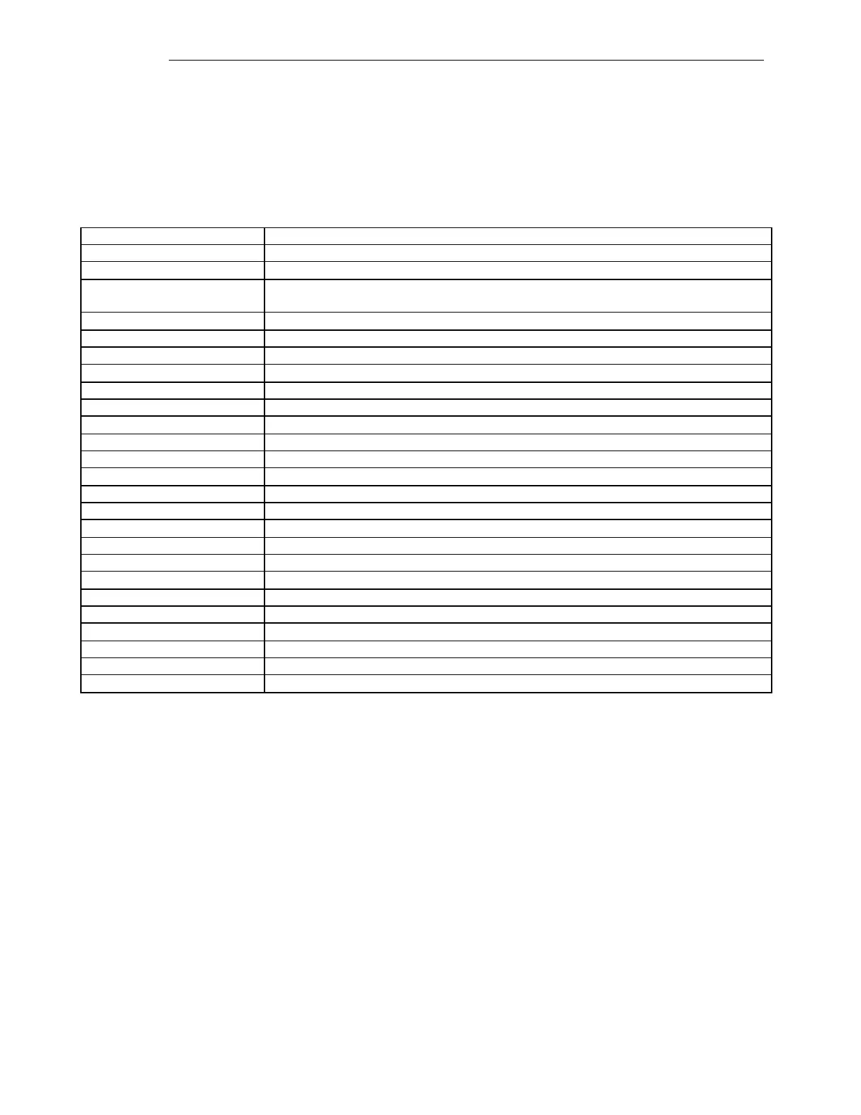
8.5.2 OUTPUT MAPPING
There are 12 discrete outputs in the default configuration. Each of those outputs can be driven by one
of the following sources. Only one source can drive an output and each source can drive only one
output. In the following table, N can equal any function from 2 to 8.
Table 8-12. Output Mapping
This indicates that this output is never driven active
This is the function receive trip output
This is the unblock trip output. After the unblock security time (20 ms) of failed
channel, this goes active for the unblock delay time (150 ms).
This goes active when a local trip is sent or when the receive trip goes active.
These go active when channel 1 senses communication errors
Trip signal from the distance protection module
Trip signal from the distance protection module
Retrip signal from the breaker failure protection
Retrip signal from the breaker failure protection
Breaker Failure Relay Pick-up signal
Breaker Failure Relay trip signal
Breaker Failure Relay trip signal
Breaker close signal from the autorecloser
Breaker close signal from the autorecloser
Trip signal from rate of change of frequency function, step 1
Trip signal from rate of change of frequency function, step 2
Trip signal from rate of change of frequency function, step 3
Trip signal from the under frequency function, step 1
Trip signal from the under frequency function, step 2
Trip signal from the under frequency function, step 3
Trip signal from the over frequency function, step 1
Trip signal from the over frequency function, step 2
Trip signal from the over frequency function, step 3
Trip signal from the Breaker Monitor for excess number of trips
Trip signal from the Breaker Monitor for excess accumulated breaking current