System Logic
GARD 8000 SYS RFL Electronics
March 26, 2008 8-7 973.334.3100
8.2.9 TIMER
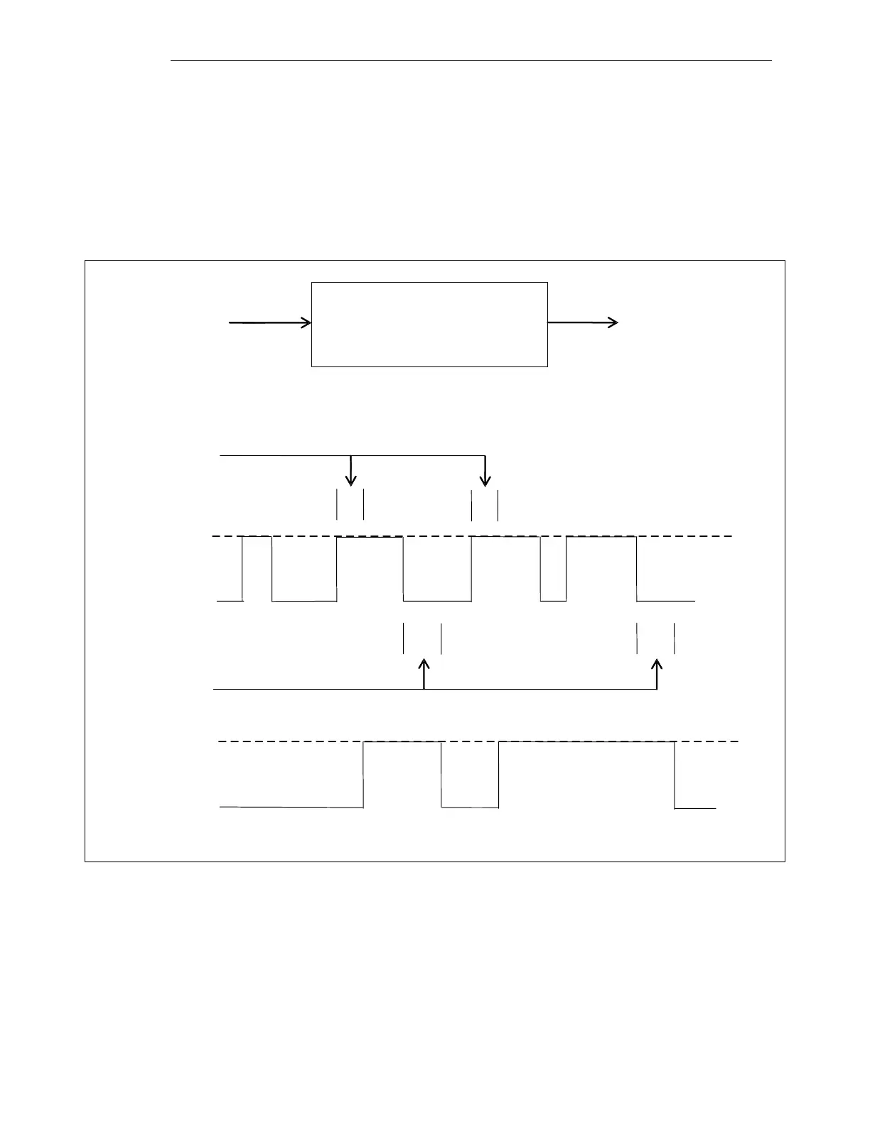
A timer has one input and one output, as shown in Figure 8-9. The output tracks the input after a given
time delay. Each timer has two settings: "attack time" and "decay time." If the input goes true, the
output will go true after a time delay equal to the attack time, as long as the input is still true; if the
input is not true at the end of the attack time, the output will not change. If the input goes from true to
false after the attack time has been satisfied, the output will go false after a time delay equal to the
decay time. If the input remains false less than the decay time, the output will not go false.
INPUT
OUTPUT
ATTACK TIME
a. Symbol
b. Timing Diagram
TRUE
TRUE
FALSE
FALSE
DECAY TIME
INPUT
OUTPUT
TIMER #
GATE #
ATTACK/DECAY VALUES (in ms)
Figure 8-9. Timer


 To Next Page