System User Interface
GARD 8000 SYS RFL Electronics
August 1, 2012 5-4 973.334.3100
NET
RJ- 45
Ethernet
Port
RESET
PWR
GARD 8000
Protective System
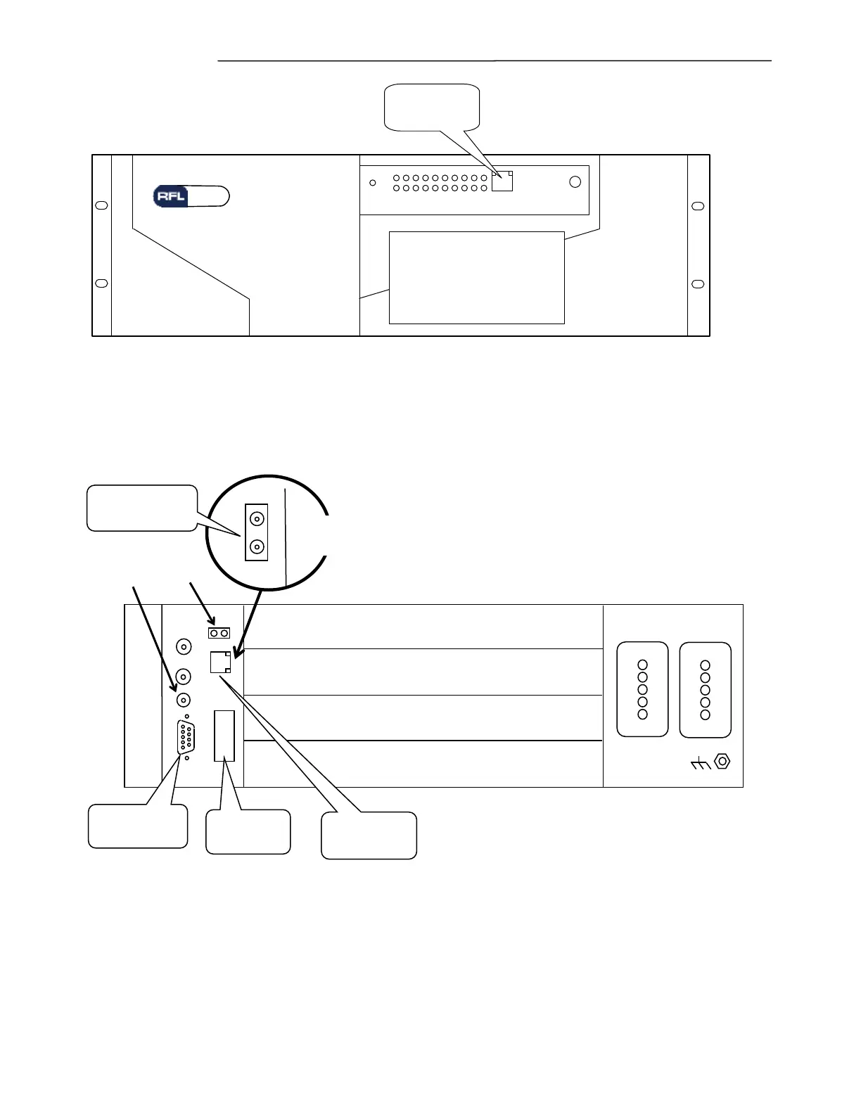
Figure 5-4. Front view of 3U chassis showing the location of the RJ-45 port
Figure 5-5. Rear view of 3U chassis showing the location of the RJ-45 (or Fiber Optic) and the RS-232 ports
A valid Ethernet connection is one that has the Link established, and is represented by a solid light (or
blinking light) on the left LED of the connector.
POWER SUPPLY 1 POWER SUPPLY 2
ALARM
ALERT
Optional System I/O Module has Fiber
Optic connectors instead of RJ-45
Input From
Optional GPS
Antenna

 Loading...