System Logic
GARD 8000 SYS RFL Electronics
March 26, 2008 8-1 973.334.3100
SECTION 8. SYSTEM LOGIC
8.1 LOGIC OVERVIEW
The GARD 8000 relies on logic to interconnect the modules and implement logical operation on the
signals. Users familiar with the 9745 will find this concept similar but enhanced. The logic is custom
designed for each configuration of modules and user requirements. The logic is provided to the user in
the form of a PDF logic diagram. This diagram defines the operation of the system.
The logic diagram may consist of several sheets with a hierarchical structure. In a hierarchy, blocks
that appear on higher level sheets represent additional sheets containing low level logic diagrams.
8.2 LOGIC GATES
The GARD 8000 logic consists of inputs from the system, combined using logic gates, driving outputs
to the system. The following gates are defined for use in a logic diagram.
Two and Three input AND gates
Two and Three input OR gates
Inverter (not)
Exclusive OR gate
Timer
Latch
Buffer
Toggle
True
False
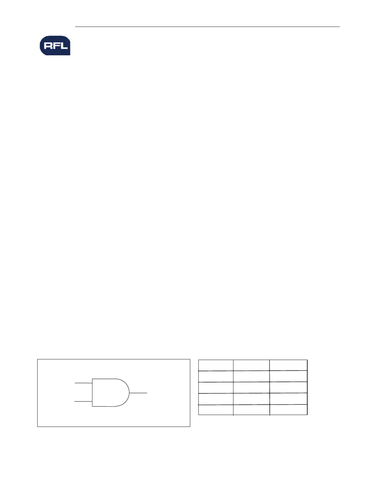
8.2.1 TWO INPUT AND GATE
A two input AND gate has two inputs and one output, as shown in Figure 8-1. If both inputs are true,
the output is true. If either input is false, the output is false.
Table 8-1. Truth table for Two Input AND gate
INPUT 1
INPUT 2
OUTPUT
Input 1
Input 2 Output
False
True
True
False
False
True
True
False
False
False
False
True
Figure 8-1. Two input AND gate
 Loading...