Installation and Commissioning
GARD 8000 SYS RFL Electronics
November 28, 2017 4-52 973.334.3100
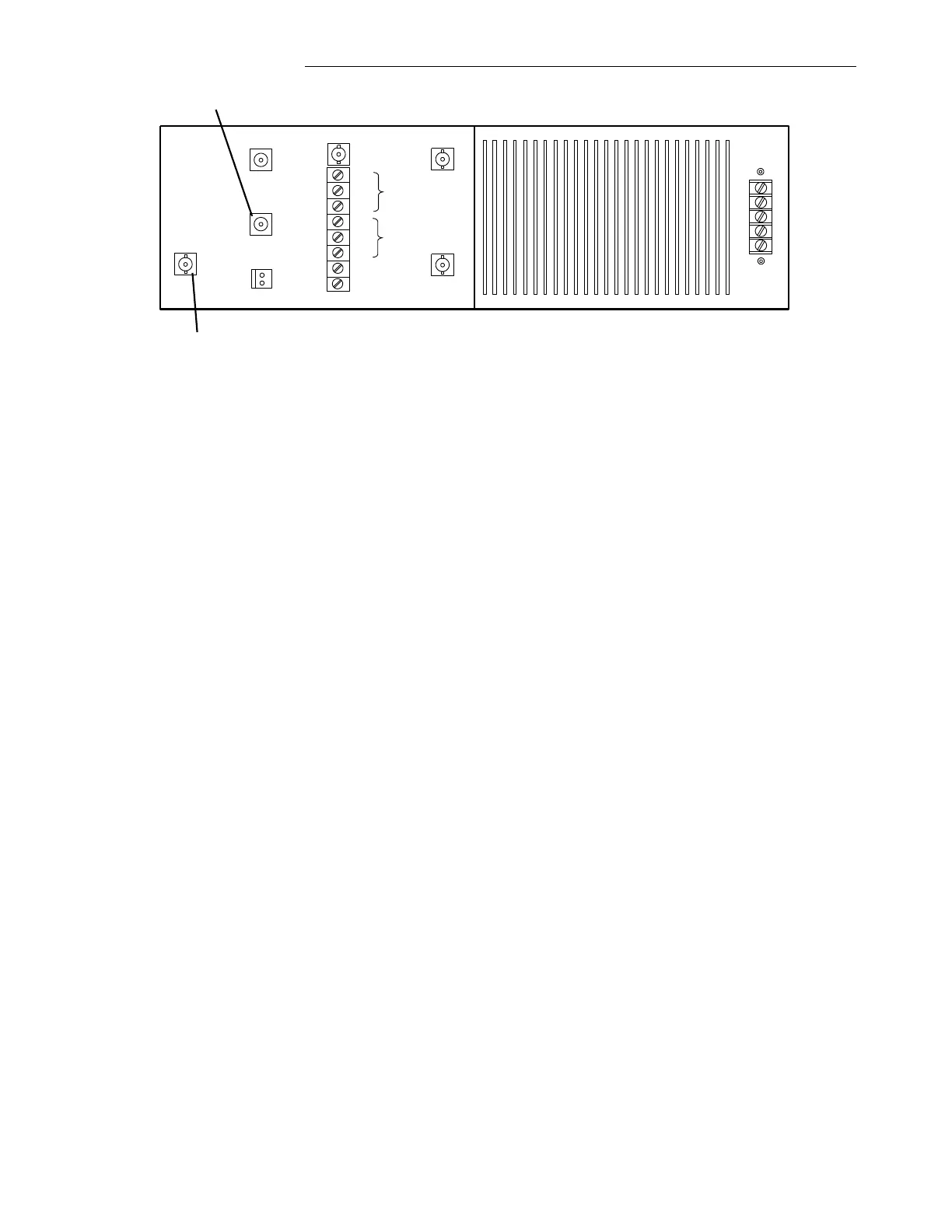
EXT AMP IN
TX IN
EXT AMP
OUT
EXT AMP
FAIL IN
C
NO
NO
C
NO
NC
EARTH GND
4W RX
INT
AMP
FAIL
EXT
AMP
FAIL
V+
V-
C
NO
NC
2W 1/O Connector
RX Out BNC
Figure 4-19. PLC Rear of 50W RF Chassis
15. Verify the level across the dummy load using a FSVM.
a. When transmitting 5 watts verify 14.0Vrms (+35.5dBm) to 15.8Vrms (+37dBm) across
dummy load.
b. When transmitting 10 watts verify 20.0Vrms (+38.5dBm) to 22.3Vrms (+40dBm) across
dummy load.
c. When transmitting 50 watts verify 44.0Vrms (+45.4dBm) to 50.0Vrms (+47dBm) across
dummy load.
d. When transmitting 100 watts verify 55.0Vrms (+48.0dBm) to 70.7Vrms (+50dBm) across
dummy load.
The Transmit carrier output level should now be aligned for proper operation.
1. Remove connector J5 from the Power Amplifier Circuit Board.
2. Disconnect the dummy load from the carrier output connector and reconnect the coax from the
carrier set to the line tuner.
3. Reinstall the connector at J5.
4. Adjust the Line Tuning Units for minimum reflected power according to the manufacturer’s
recommendations.
A Reflected Power reading of <4% or 14dB (forward & reverse) should be achieved for
optimum performance.
5. Trans-hybrid adjustment: