Module Descriptions
GARD 8000 SYS RFL Electronics
April 23, 2015 6-18 973.334.3100
the front of the chassis, and the Analog PLC module plugs into the rear of the chassis. The Analog
module occupies two adjacent module slots and must be situated directly behind the Digital module.
6.5.1 PLC DIGITAL MODULE
The PLC Digital module (500455) has eight LEDs and five test points on its front edge. See Table 6-9
and Figure 6-8 for the locations and descriptions of controls and indicators for this module.
6.5.2 PLC ANALOG MODULE
The PLC Analog module (500935 and 500930) have a rear panel with two BNC RF connectors labeled
Tx and Rx, a fine and course control, and a six pin plug-in connector for an optional external power
supply and CLI connections. Listed below are the various configurations currently available with their
appropriate dash number. Refer to Table 6-10 and Figure 6-9 for additional information.
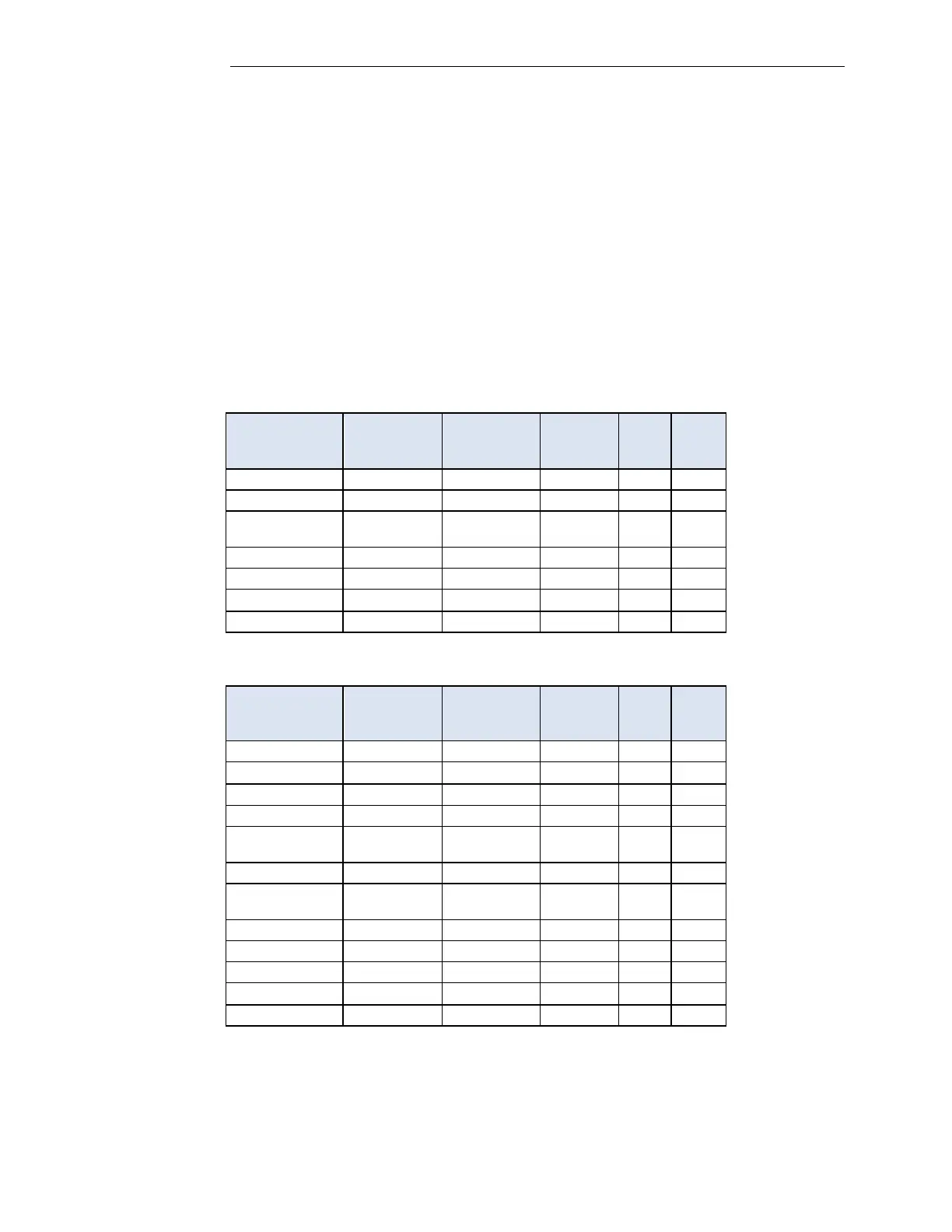
Table 6-8. PLC Analog Module Assembly Part Numbers (500935)
Table 6-9. PLC Analog Module Assembly Part Numbers (500930)