System Logic
GARD 8000 SYS RFL Electronics
March 26, 2008 8-15 973.334.3100
8.4 DEFAULT TPS LOGIC
The following section gives examples of possible default logic address schemes that can be used on the
Base 8-Bit GARD 8000 TPS System. This information is for reference only.
The 96-Bit TPS System provides inputs and outputs over a single channel of transfer trip and
can have up to 96 functions. Reference information on this system is not provided here.
The default TPS only logic in the GARD 8000 provides 12 inputs, 2 channels of transfer trip, each
with 8 transfer functions, and 12 outputs. The following tables describe the signals and configuration
settings. The logic diagrams should be referenced to for additional information.
8.4.1 INPUT MAPPING (BASE 8-BIT SYSTEM)
Each of the following signals can be driven by any of the discrete hardware inputs 12 inputs and True
or False. One hardware input can drive more than one signal. In the following table, N can equal any
function from 1 to 8.
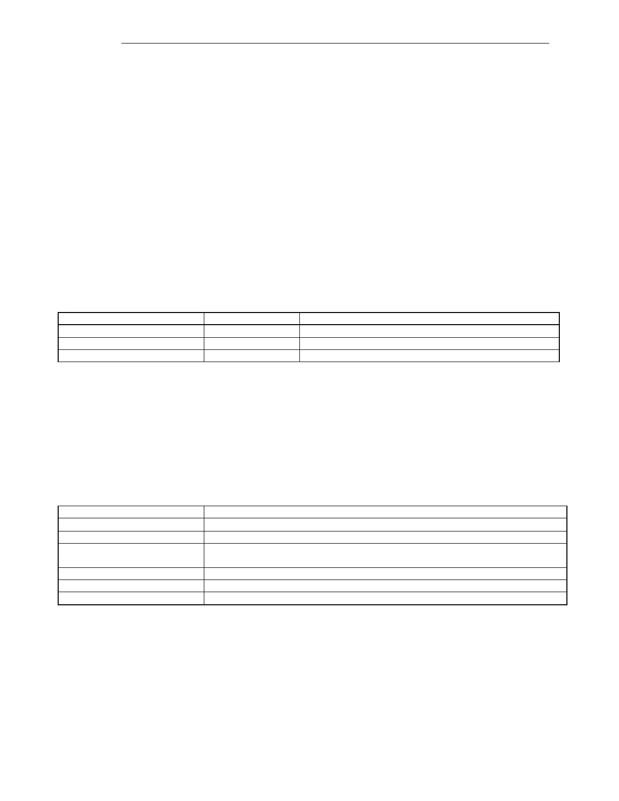
Table 8-7. Input Mapping
First Input to the function N transmit AND/OR gate
Second Input to the function N transmit AND/OR gate
Input to the function stop N transmit control
8.4.2 OUTPUT MAPPING (BASE 8-BIT SYSTEM)
There are 12 discrete outputs in the default configuration. Each of those outputs can be driven by one
of the following sources. Only one source can drive an output and each source can drive only one
output. In the following table, N can equal any function from 1 to 8.
Table 8-8. Output Mapping
This indicates that this output is never driven active
This is the function receive trip output
This is the unblock trip output. After the unblock security time (20 ms) of failed
channel, this goes active for the unblock delay time (150 ms).
This goes active when a local trip is sent or when the receive trip goes active.
These go active when channel 1 senses communication errors
These go active when channel 2 senses communication errors


 To Next Page