Installation and Commissioning
GARD 8000 SYS RFL Electronics
November 28, 2017 4-13 973.334.3100
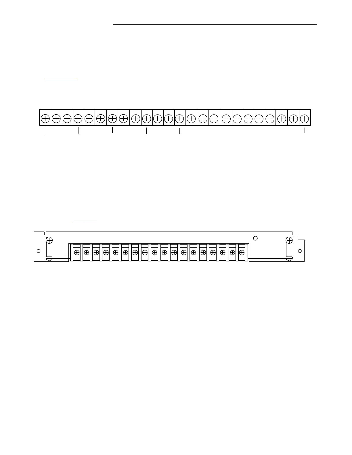
4.5.8 METERING MODULE CONNECTIONS (OPTION)
The Metering Module receives inputs from Potential and Current Transformers. Connections are made
to the rear of the GARD chassis as show below. Note that the Metering Module is in the vertical
position for the 6U chassis and horizontal for the 3U chassis, the terminal assignments are the same.
See Chapter 15. for a detailed description of the GARD Metering Module.
12346 58910 714 13 12 1118 17 16 1521 20 19222324
Chassis
GND
VA+
VC+
VC-
VA-
VB+
VB-
Chassis
GND
IA+IA-IB+
Chassis
GND
IB-
IC+
Chassis
GND
IC-
Chassis
GND
Chassis
GND
Figure 4-10. Terminal Block Connections, Metering Module
4.5.9 TELEMETRY TRANSMITTER MODULE CONNECTIONS (OPTION)
The Telemetry Transmitter Module receives DC analog inputs as defined by the user. Connections are
made to the rear of the GARD chassis as show below. Note that the Telemetry Transmitter Module is
in the vertical position for the 6U chassis and horizontal for the 3U chassis, the terminal assignments
are the same. See 6.13 for a more detailed description of this module.
500950
IN1
+
-
+
+
IN2
IN3
IN4
IN5
IN6
IN7
IN8
CAL
+
+
+
+
+
+
-
-
-
-
-
-
-
-
-
Figure 4-11. Terminal Block Connections, Telemetry Transmitter Module