Module Descriptions
GARD 8000 SYS RFL Electronics
April 23, 2015 6-31 973.334.3100
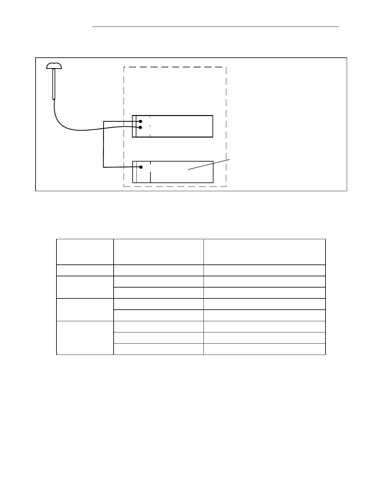
Jumpers on the second GARD System I/O module must be set as shown in Table 6-13 when a GPS
receiver is connected as shown below.
Rear of GARD unit 1
Rear of GARD unit 2
GPS
GPS Receiver
Substation
IRIG-B out
IRIG-B in
The second GARD unit must have
the jumpers set on the System I/O
module as shown below.
Figure 6-16. IRIG-B with GPS
Table 6-14. System I/O jumper settings, IRIG-B connected to
second GARD unit, first unit has GPS receiver installed.
Jack Number (See
figures 6-13 or
6-15 as applicable)
Jumper Installed across these
two terminals (See figures 6-13
or 6-15 as applicable)
IN - IRIG-B, AGC is bypassed
IN - For Unmodulated IRIG-B inputs
IN - 600 Ohm IRIG-B termination
IN - IRIG-B shield is grounded
IN - 600 Ohm 1PPS termination
All other jumpers should be removed (no connection).
6.7 DISCRETE I/O BASE MODULE AND I/O MODULES
 Loading...