Module Descriptions
GARD 8000 SYS RFL Electronics
April 23, 2015 6-1 973.334.3100
SECTION 6. MODULE DESCRIPTIONS
This section discusses the major modules used in the GARD 8000 system. These modules are listed in
Table 6-1 below, which includes assembly numbers, and where to find additional information. The
Base System modules have fixed locations (slots) in the chassis and the Interface modules can be
located in any free slot. The 3U chassis has four slots numbered 1 through 4, and the 6U chassis has
eleven slots numbered 1 through 11. Refer to Figures 6-1 and 6-2 for module and slot locations.
Most rear panel modules can be removed from the chassis using an extraction tool (103977) which
threads into a threaded hole in the rear panel of the module. The tool is then pulled to extract the
module.
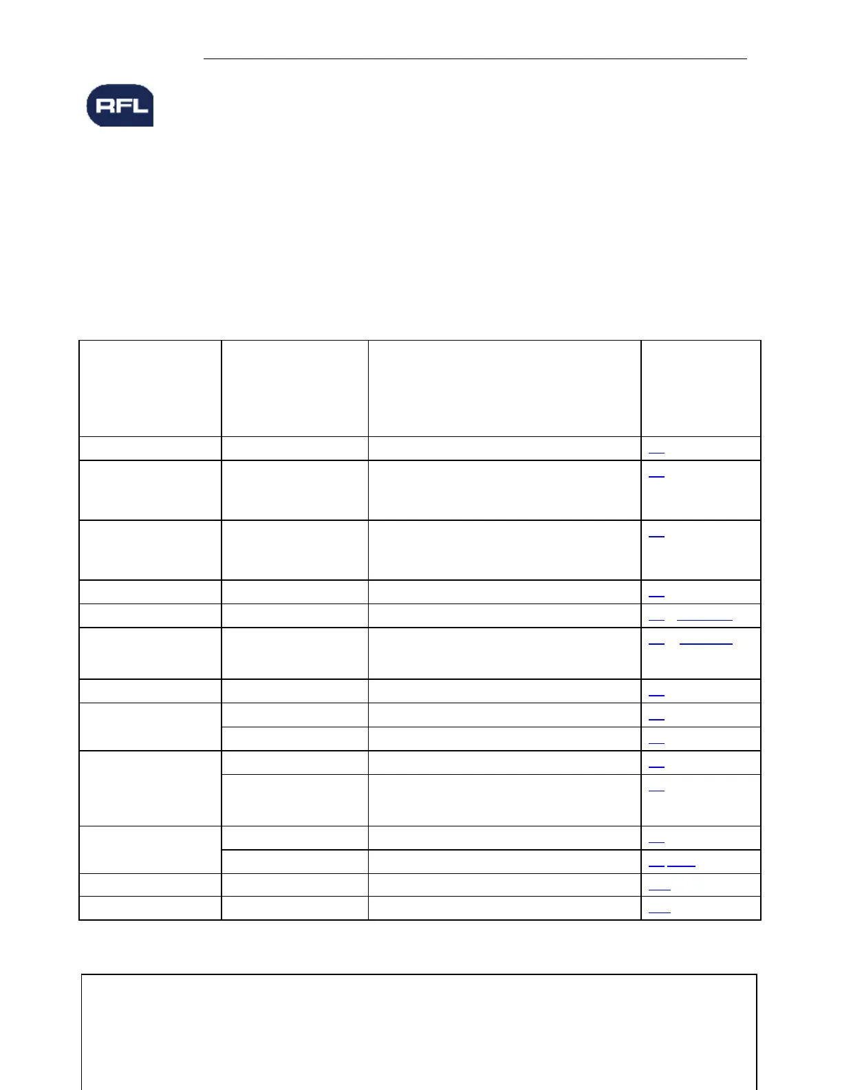
Table 6-1. GARD 8000 System Modules
For Additional
Information
Refer To The
Following
Sections
500410-5 Base System
500410-1 Optional 96-Bit TPS
500410-4 Optional Display with 9745 Emulation
500500 Base System
500500-1 Optional 96-Bit TPS, 50040-3 G.703
500500-4 Optional TPS with 9745 Emulation
500930, 500930-1, 500930-2, 500930-3 500930-4,
500930-10, 500930-11, 500930-20, 500930-21,
500930-22, 500930-23, 500930-30
500430-1, 500435, 500435-1, 500420-1, 500425-1
500805, 500805-1, 500810, 500815,
500855, 500860-1, 500865, 500870, 500875,
50075-1, 500880, 500885, 500890, 500890-1,
500945
500310-2, 500310-3, 500310-4, 500310-5
106510-3, 106510-4, 106510-5, 106510-6
Note: If this page is being viewed as a pdf the sections and sub-sections have been hyper-linked for your convenience.
>>text continues on page 6-4<<