Module Descriptions
GARD 8000 SYS RFL Electronics
April 23, 2015 6-52 973.334.3100
6.13 TELEMETRY TRANSMITTER MODULE
This optional module will accept up to 8-channels of DC inputs and output this data digitally for use by
other facets of the GARD system. There is an additional channel used for calibration. The Telemetry
TX Module will accept voltage as an input, however current may be used instead. To achieve this,
precision resistors need to be installed in parallel with the input to convert the voltage input to a current
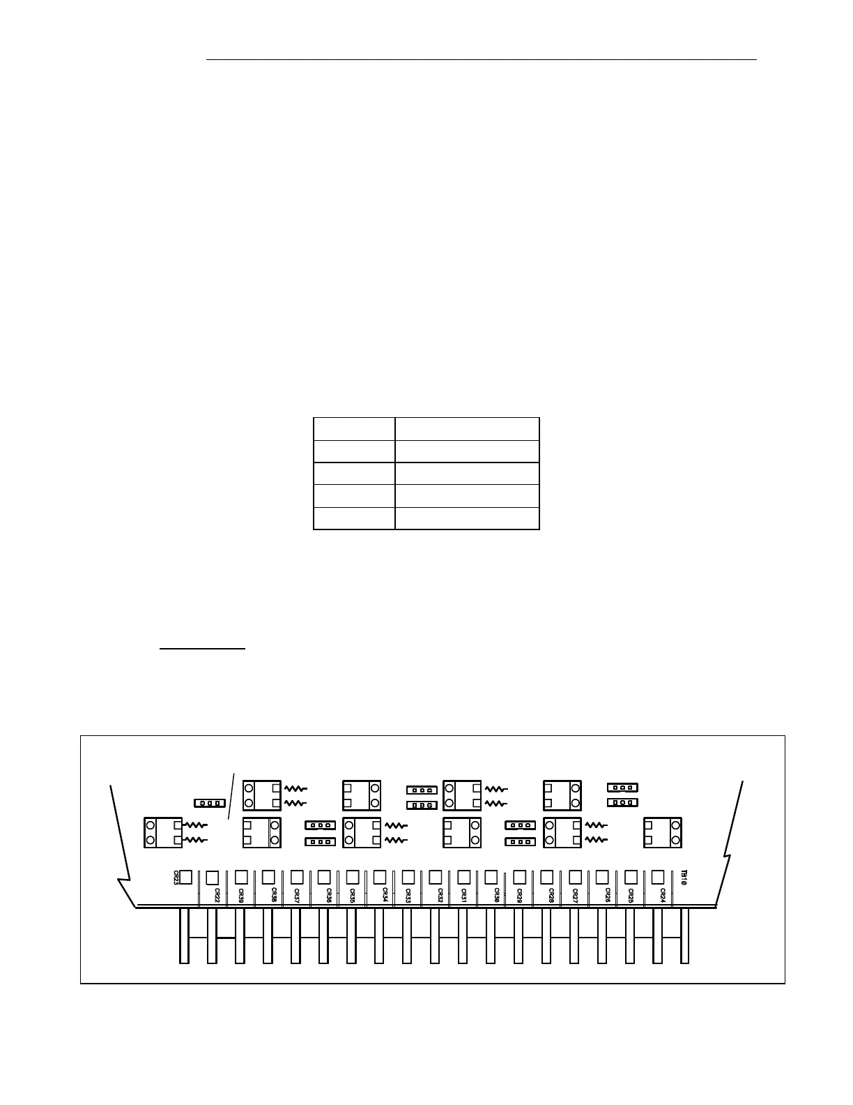
input. Optionally, jumpers J7 through J15 will tie the negative input lead of the corresponding input
channel to ground. The circuit board silkscreen indicates which resistor and jumper are for which
channel.
6.13.1 SETTING RESISTORS AND JUMPERS ON THE TELEMETRY TX
MODULE
The conversion resistors are not supplied by RFL, they should have an accuracy of 0.01% to guarantee
the system accuracy of ± 0.05%. Since the system accuracy applies to a full-scale voltage input, the
conversion resistor should be chosen so that the voltage across it is as high as practically possible and
within one of the ranges shown in the table below.
Table 6-24. Input Gain verses Input Voltage Range
Example: If an input current range of 0 to 50mA is required then a conversion resistor of 200Ω will
result in an equivalent voltage input of 0 to 10 volts at the A/D converter.
The resistor value is calculated as follows:
This is a readily available value for a precision resistor.
TB12
J7
IN1IN2IN3IN4IN5IN6IN7IN8CAL
++++++ ++ -+ --------
R CAL A
R CAL B
R CH 7
R CH 8
R CH 5
R CH 6
GND7
GND8
GND
CAL
R CH 3
R CH 4
R CH 1
R CH 2
GND5
GND6
GND3
GND4
GND1
GND2
J14
J15
J12
J13
TB8
TB9
TB7
TB6
TB4
TB5
TB2
TB3
TB1
J10
J11
J8
J9
Note, for CAL only one
resistor is required
Figure 6-27. Setting Resistors and Jumpers on the Telemetry TX Module