Current Differential Relay
GARD 8000 SYS RFL Electronics
June 20, 2014 13-79 973.334.3100
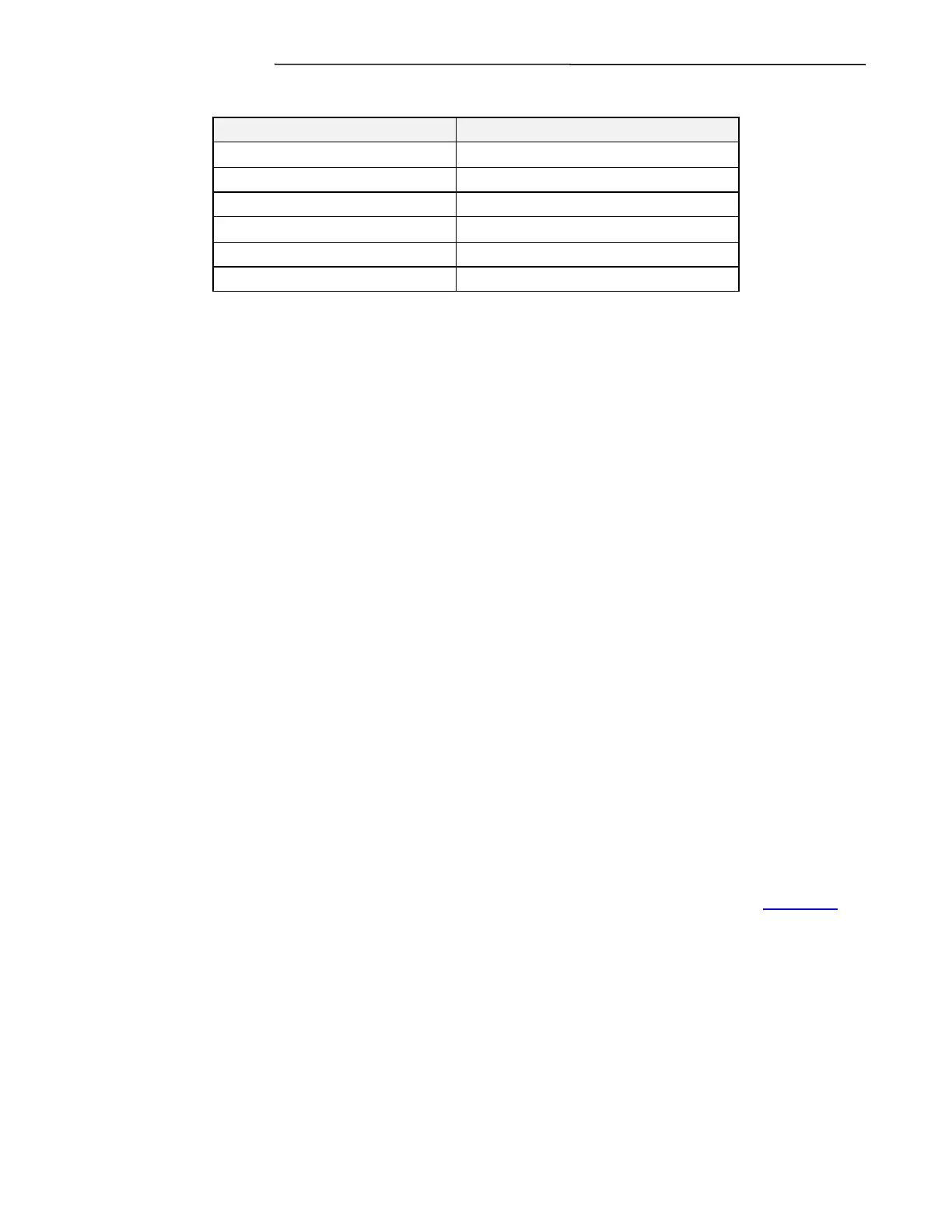
Table 13-2 Maximum Number of Oscillography Records
Set Record Length (cycles)
Approximate number of records
13.6.2.4 TRIGGER CONDITIONS
The user may configure which signals within the relay will cause an oscillography recording to be
initiated. In addition to the user selected triggers the relay sets all trips as valid oscillography triggers.
Any change of state (becoming active or inactive) of any trigger will initiate an oscillography
recording.
The selection of triggers does not impact what data is recorded in the oscillography.
13.6.2.5 RECORDED DATA
The oscillography records record 33 samples per cycle. Each sample includes all of the measured
currents (as analog measurements), all of the selectable trigger items, and a number of additional status
items (as digital measurements).
Major Alarm
A logical “1” indicates the relay has an active major alarm.
Minor Alarm
A logical “1” indicates the relay has an active minor alarm.
Curr Diff Alarms Phase, A, B, C, and Ground
A logical “1” indicates the phase in question has an active current differential alarm.
Breaker Open
There has been no current measured in any of the four inputs for a period of time.
External Dual Breaker Fault Detector
A logical “1” indicates that an external dual breaker fault has been detected. (See section 13.5.1.1.7)
Remote1 Fault Detector
A logical “1” indicates the remote relay has an active fault detector.
Comms1 Relay Configuration Mismatch
A logical “1” indicates the remote relay configuration is incompatible with the local relay (e.g. one is
single-pole the other is three-pole).
Ping-Pong Alarm Comms1
A logical “1” indicates there is a ping-pong alarm active.