Power Line Carrier
GARD 8000 SYS RFL Electronics
April 23, 2015 10-31 973.334.3100
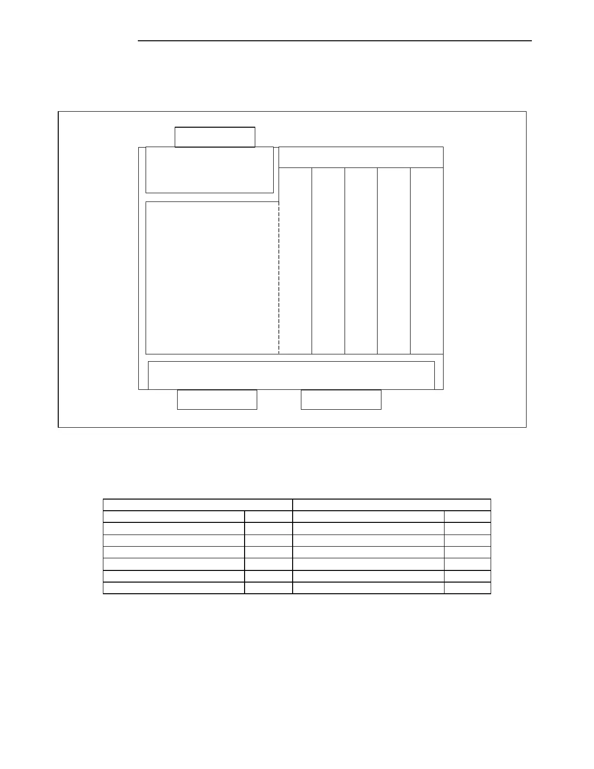
50 Watt systems are housed in a 6U high chassis. The upper part of the chassis is the RF Section, and
the lower part of the chassis is the GARD 8000. Module placement in the RF Chassis is shown below.
A typical 50 Watt RF Chassis will have modules installed as shown.
POWER AMP
POWER SUPPLY
PART OF TX FILTER
TX
FILTER
BALANCE BOARD
LINE
BOARD
RX FILTER orRX CONNECTION BOARD
ATTENUATOR
50W POWER AMPLIFIER
REAR
Figure 10-22. Module Placement in a Typical 50W 9508 RF Chassis (Top View)
Table 10-13. Module Placement in the RF Chassis (50W System)
Power Amplifier Power Supply