Installation and Commissioning
GARD 8000 SYS RFL Electronics
November 28, 2017 4-31 973.334.3100
-V (AC/DC)
Ground
!
+V (AC/DC)
C
C
NC
NO
NC
NO
POWER SUPPLY 1
POWER SUPPLY 2
MAJOR
MINOR
RS-499
X.21
V.35
1
1
0 0
38 - 150/200-300 VDC
220 W MAX.
3AMPS
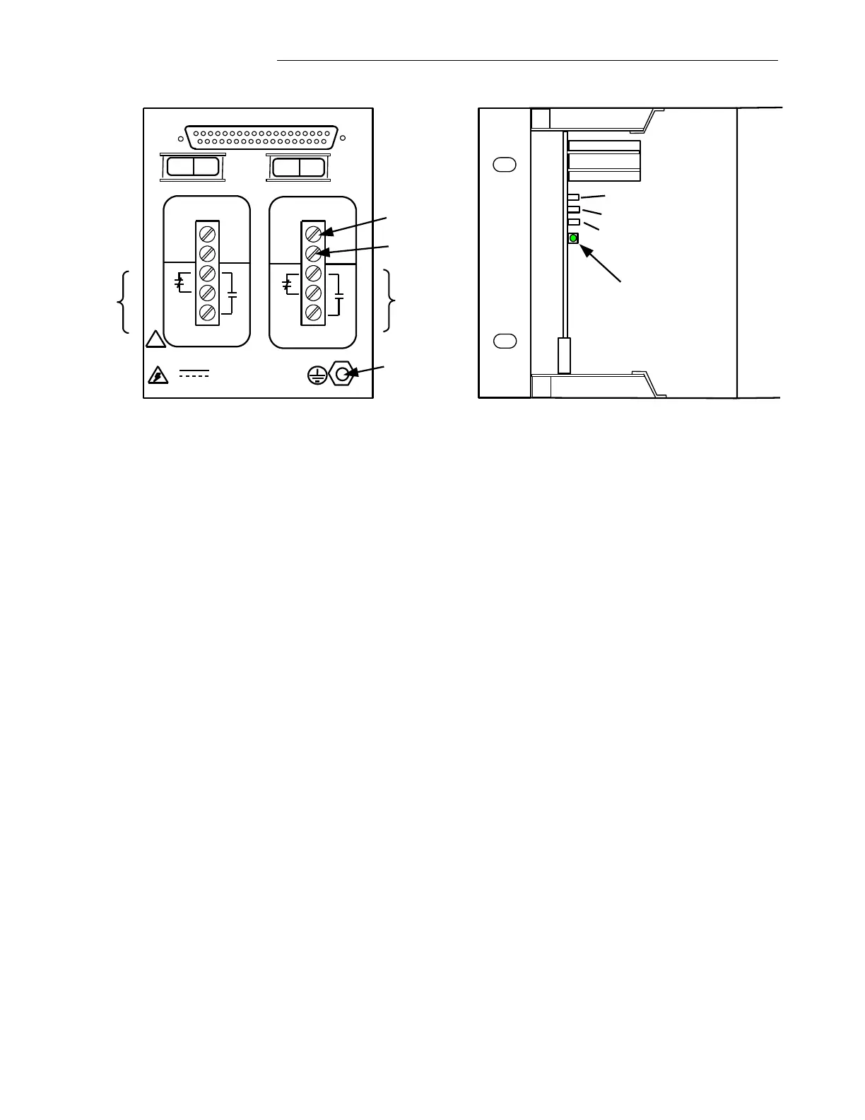
Rear View, Power Supply I/O Module
3U Chassis
DS1
Front View, Power Supply PCB
3U Chassis, Front Cover Removed
TP 1Test Point(+V)
TP 2 Test Point(GND)
TP 3 Test Point(-V)
Figure 4-14. Power Supply I/O Module (Audio-Tone Commissioning)
GARD 8000 Boot Up Sequence
With the front panel open, verify that a boot up is in progress as displayed by the LEDs (DS1-DS4) on
the Controller Module.
a. During the multiple stages of the boot-up process the DS1 and DS2 indicators will change
colors (starting red, yellow and green). A Solid Green LED of DS1 indicates a final boot up
has been successfully completed.
b. The complete boot-up process will take less than 1 minute.
c. The LED DS2 indicates the status of the Front and Rear Ethernet Port. When the LED is Red,
the Ethernet cable is not connected to the Front or Rear RJ-45 Ports. If the LED is orange the
Ethernet cable is connected to the Front Port, if the LED is Green the connection is made to the
Rear Port.
d. The LED DS3 indicates a state of redundancy control. (The 3U chassis does not support
redundancy, therefore this LED under a normal condition should be solid green).
However, if this LED is Solid Orange the module has detected an on-board fault, but it
continues operating. If the LED DS3 is Red the module has detected an on-board fault
and is not functioning.
e. The LED DS4 is used for factory diagnostics only.
f. Verify the position of the Toggle Switch SW2. In the 3U chassis, SW2 should be in the
NORM position (left-front view) and not in the Disable position.
g. After a successful boot up the GARD 8000 is ready for interrogation through the front Ethernet
Port located on the DISPLAY Module.