Module Descriptions
GARD 8000 SYS RFL Electronics
April 23, 2015 6-17 973.334.3100
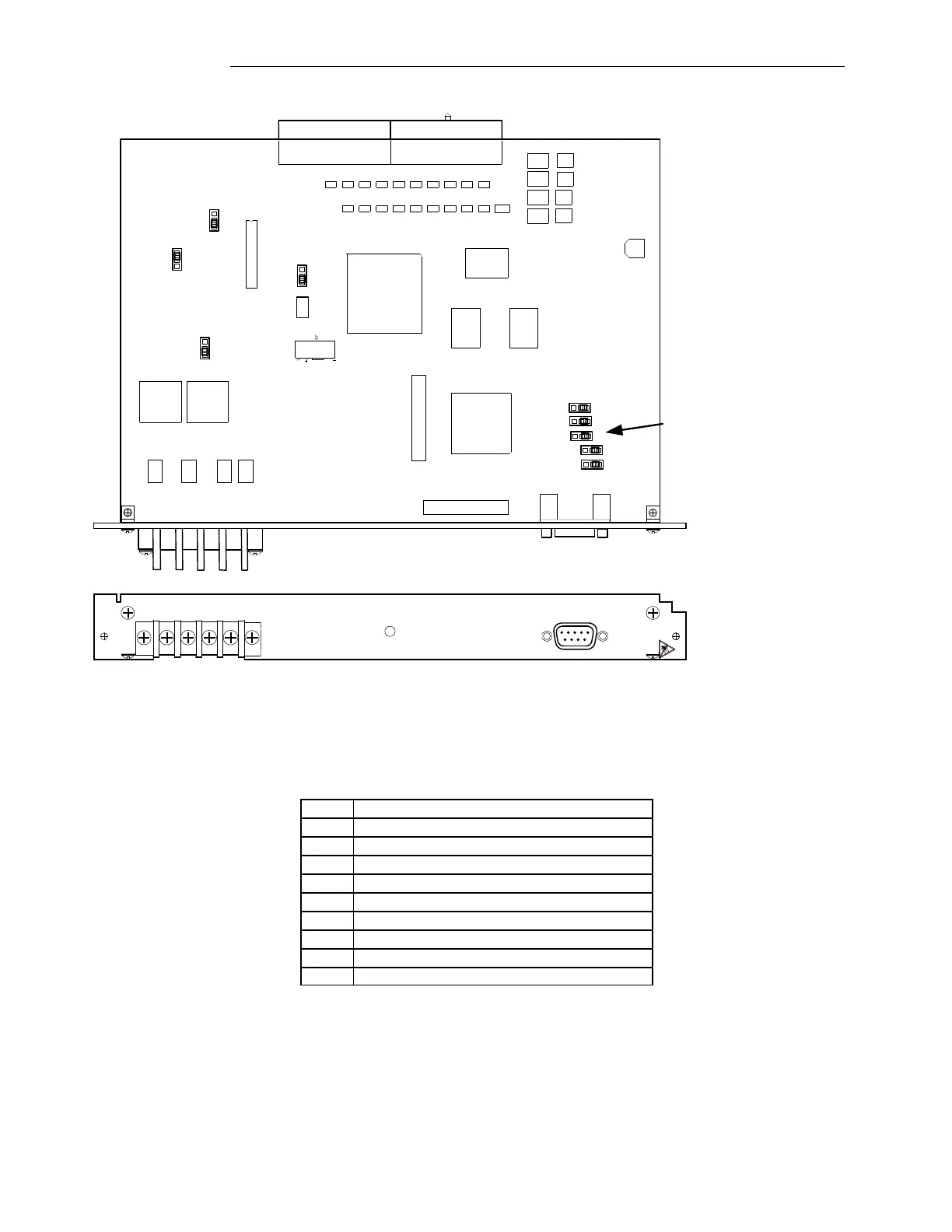
J8
60
50
J11
2W
4W
SW1
J6
WDD
NORM
J7
IN
OUT
A
J13
B
J17
J16
TB1
J9
TX (4W)
RX (4W)
TX/RX (2W)
J15
J14
AUDIO
TPS+DATA
+STATUS
Set all jumpers to 'B' if
RS-485 is used.
Default position is 'A'
Figure 6-7. Controls and indicators locator drawing for Audio Tone TPS module
Table 6-7. RS-232/485 connector pin-outs
TX Data B+ (RS-485 output)
RX Data B- (RS-485 input)
TX Data B- (RS-485 output)
RX Data B+ (RS-485 input)
6.5 POWER LINE CARRIER MODULES
GARD 8000 Systems with Power Line Carrier (PLC) capability are equipped with a PLC module set
consisting of a Digital PLC module and an Analog PLC module. The Digital PLC module plugs into