Power Line Carrier
GARD 8000 SYS RFL Electronics
April 23, 2015 10-27 973.334.3100
10.8.5.1.5 Impedance Matching Transformers
Impedance matching transformers T1 and T2 match the impedance of the Line Board to that of the
line. Jumper J10 selects one of T1’s four impedance settings: 50, 75, 100, or 130 ohms. Fuse F1
provides current protection, and surge arrestor E2 protects the equipment against an overvoltage
condition. Jumper J20 selects one of T2’s four impedance settings: 50, 75, 100, or 130 ohms. Fuse F2
provides current protection, and surge arrestor E1 protects the equipment against an overvoltage
condition. In 2 wire applications, the signal going to or coming from the line coupling equipment can
be monitored at test point TP2. In 4 wire applications, the signal going to the line coupling equipment
can be monitored at test point TP2, and the signal coming from the line coupling equipment can be
monitored at test point TP3.
10.8.6 RX FILTER
The function of the Rx Filter is to prevent harmonics and noise from coming into the GARD 8000 PLC
from the power line that is out of the bandwidth of the filter. The bandwidth of the Rx Filter can be set
to either 8kHz or 16kHz using two programmable jumpers on the board. The filter center frequency is
tunable from 24kHz to 496kHz using programmable jumpers. The outer edges are 20kHz and 500kHz.
The 8kHz bandwidth is used for most applications. The Rx Filter Board is optional and is typically
replaced with the Rx Connection Board.
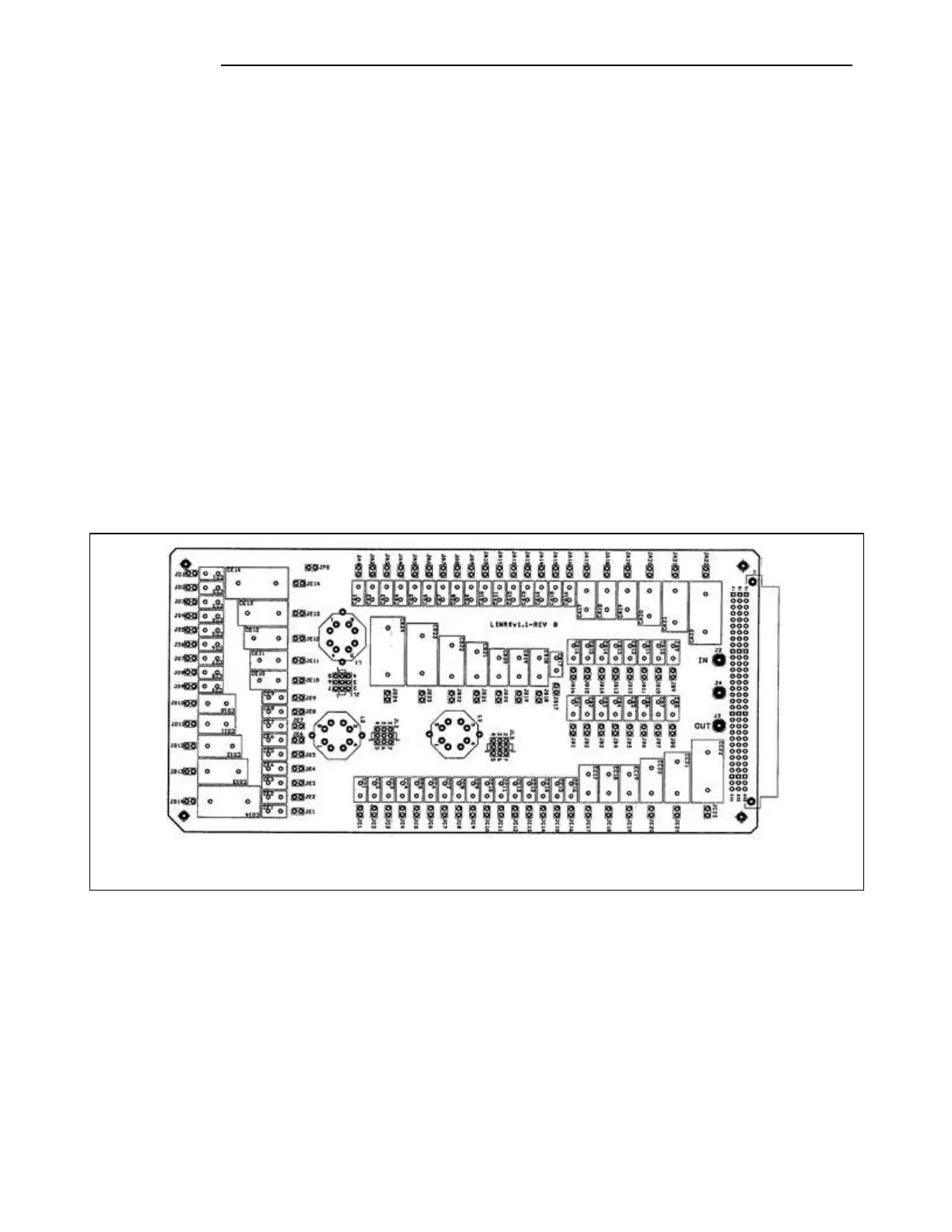
Figure 10-18. RFL 9508 RX Filter Board