Power Line Carrier
GARD 8000 SYS RFL Electronics
April 23, 2015 10-21 973.334.3100
+BATTERY
-B ATTERY
PW R FAIL-C OM
PW R FAIL NO
PW R FAIL NC
TB1-1
TB1-2
TB1-3
TB1-4
TB1-5
+BATTERY
-B ATTERY
PW R FAIL-C OM
PW R FAIL NO
PW R FAIL NC
TB1-1
TB1-2
TB1-3
TB1-4
TB1-5
ADDITIO N AL 3U CHASSIS FOR 100W SYSTEM S
EXT AMP F A IL C OM
EXT AMP F A IL -NC
EXT AMP F A IL -NO
IN T A M P F AIL C OM
IN T A M P F AIL -NC
IN T A M P F AIL -NO
IN P U T P O R T 1
SIG N A L O U T
IN P U T P O R T 2
BALA N CE T R A N SFORMER
RX CONNEC TION BOA R D or RX F ILTER
DUM M Y L O A D & AT TENUATO R
ADJUSTA B LE ATTENUA TO R
IM PE D ANCE M A TCHIN G _ 1
TX INPUT
BALANCE PORT
SIG NAL OUT
RX OUTPUT
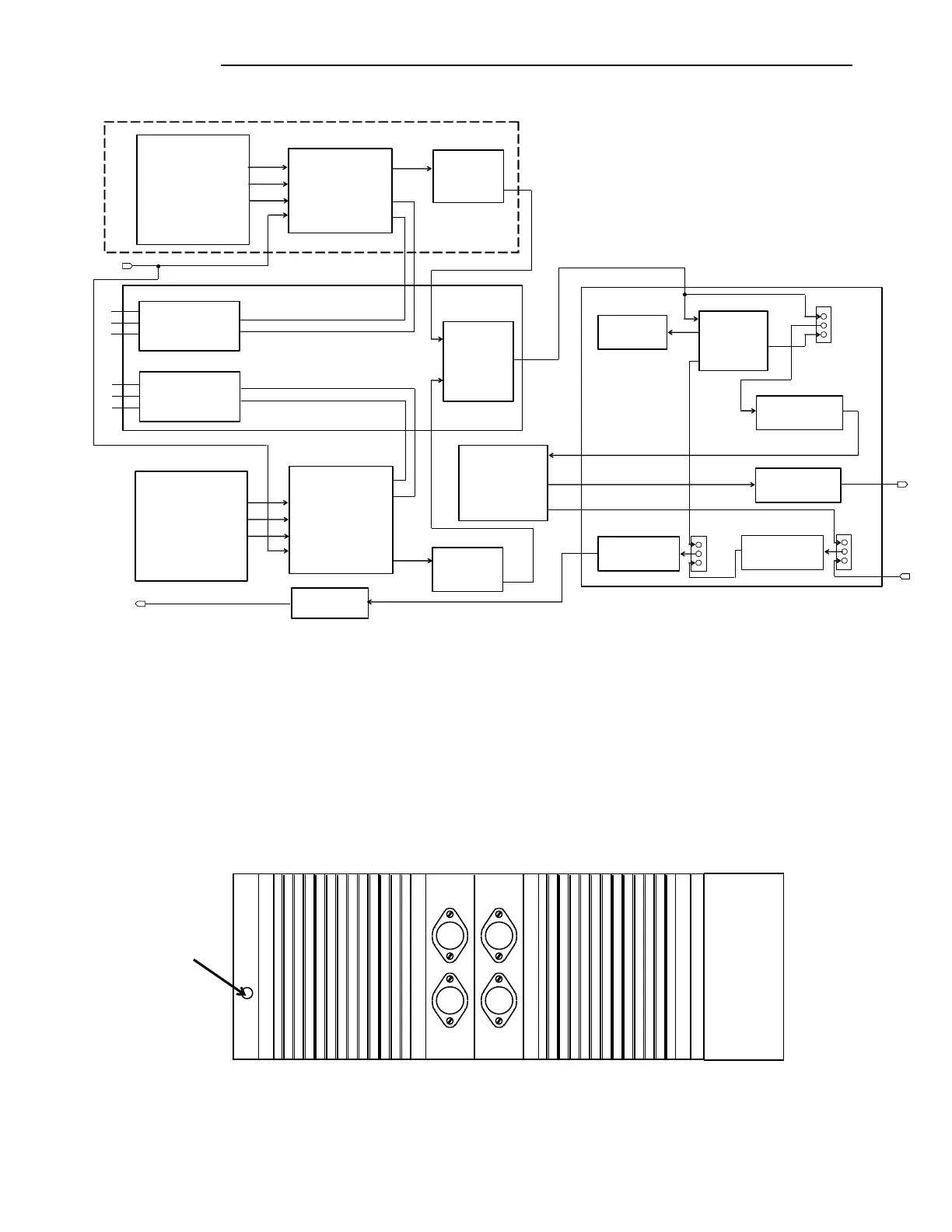
Figure 10-10. 9508 RF Chassis Block Diagram
10.8.1 50 WATT POWER AMPLIFIER
The Power Amplifier is mounted on the front cover of the 9508 RF Chassis. The function of the Power
Amplifier is to amplify the RF outputs of the GARD 8000 before these signals are passed to the line
coupling equipment. The Power Amplifier develops an RF output of 50 Watts. A green LED is located
on the left side of the Power Amplifier front panel as shown in the Figure below. The LED is ON when
the power amplifier is transmitting.
Figure 10-11. 9508 RF Chassis Power Amplifier
In those applications that require 100 Watts of RF output, two 50 Watt Power Amplifiers are used. The
second 50 Watt Power Amplifier is mounted in a 3U chassis directly above the RFL 9508 chassis as