GARD DNP Configuration and SNMP Trap Agent
GARD 8000 SYS RFL Electronics
April 23, 2015 16-19 973.334.3100
Note 1. In the example shown the community name is designated as ‘Public’ for all 3 Trap Receivers,
however if the receivers need to be differentiated the names can be unique for each receiver.
16.5.3 HMI OUTPUT CONSIDERATIONS
When the Trap Agent receives an HMI output change notification, it processes each bit of the 64 bit
change mask. For each bit set in the change mask, it produces one SNMP Trap Message and sends
that message to all enabled SNMP monitoring computers. One bit change mask can have from one to
64 bits set, with all monitoring computers enabled the Trap Agent will generate up to 320 Trap
Messages. Each Trap Message will contain:
The HMI-OUT bit number
The HMI-OUT bit value (after the change)
The HMI-OUT bit label
The RTC based time -stamp
The three User System Labels as set in the System Configuration page.
(To aid in identifying which GARD event is sent to the Trap)
HMI output bits are completely defined by the GARD logic. One should consider creating custom
logic to generate HMI output bit changes that facilitate reporting of events important at the monitoring
stations.
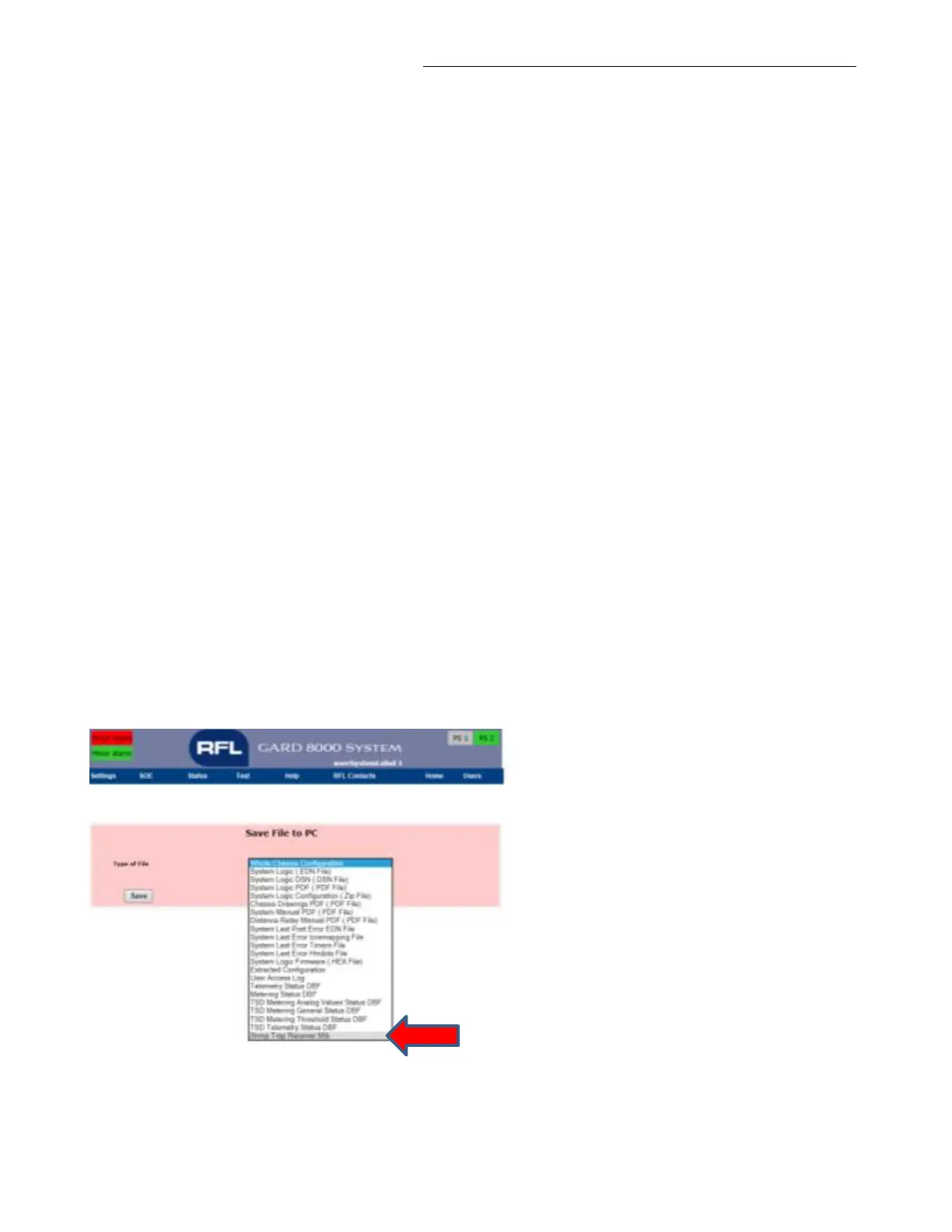
16.5.4 DOWNLOADING MIB FILE FOR SNMP TRAPS
From the “Chassis Configuration Status” page go to Settings > File Operations.
Select “Snmp Trap Receiver Mib” and save the file to your PC or Laptop.
Figure 16-14. Enabling the Trap Receiver MIB