System Logic
GARD 8000 SYS RFL Electronics
March 26, 2008 8-6 973.334.3100
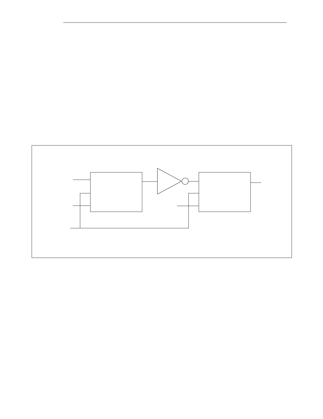
8.2.8 TOGGLE GATE (THREE INPUTS, ONE OUTPUT)
The Toggle primitive takes two inputs and forms a toggle gate as shown in Figure 8-8. If the first input
(clock) changes from FALSE to TRUE (rising edge), and the second input (RESET) is FALSE, the
output will toggle. If the second input (RESET) is TRUE, the output will always be FALSE. The
RESET input has no effect the rising edge requirement for the clock input. As a specific example, if
the clock input is TRUE and the reset is TRUE, when the reset goes FALSE the output will remain
FALSE. The clock input must be FALSE and then become HIGH to toggle the output after the reset is
released. The third input is used to set the initial condition of the rising edge detector. If the third
(initial state) input is TRUE and the clock input is TRUE when the logic primitives first starts to run,
the first TRUE clock does not toggle the output. If the (initial state) input is FALSE and the first clock
input is TRUE, the output will toggle as the primitive logic first starts to run. In all cases, if the RESET
is TRUE the output will be FALSE and the initial condition is not important. The initial state will in
almost all cases be set to zero and the reset should be used to clear the function.
TOGGLE
CLK
OUT
RST
INIT
FALSE
TRUE
TOGGLE
CLK
RST
INIT
OUT
Figure 8-8. Toggle Gate