Installation and Commissioning
GARD 8000 SYS RFL Electronics
November 28, 2017 4-7 973.334.3100
38-150/200-300 VDC
3 AMPS 220 W MAX.
!
MAJOR
MINOR
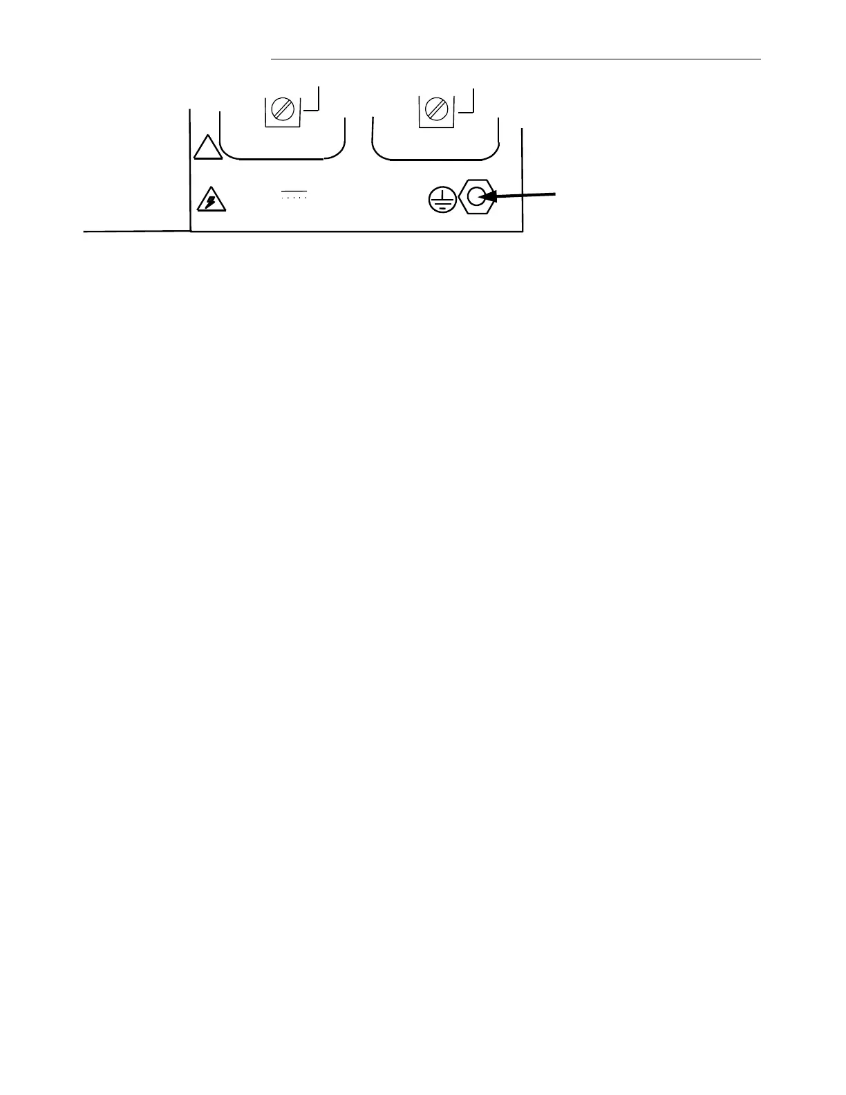
Protective Earth Stud
Figure 4-2. Location of Protective Earth Stud
Grounding is accomplished by connecting a wire 6AWG or larger between this protective earth stud
and rack ground. The grounding wire should be kept as short and straight as possible, to keep its
resistance and inductance to a minimum.
Before attempting to make power connections, make sure the GARD 8000 terminal is equipped with a
power supply designed to operate at the available input supply voltage. This can be determined by
checking the model designator on the module handle. If an external power supply is being used, check
the markings on the external power supply. If the wrong voltage is connected to the power supply,
component damage will result.
4.5.4 FIBER OPTIC CONNECTIONS
If your GARD 8000 is equipped with Fiber Optic Modules, fiber optic connectors must be connected
to the fiber optic heads on the rear panel of the GARD 8000. Type ST series bayonet fiber optic
connectors (or their equivalent) are used with both singlemode and multimode fibers. The exact mating
connector used will depend upon the head that is installed in the fiber optic module, and the specific
optic cable being used. When connecting fiber optic cables, make sure the connectors are properly
aligned before tightening and then fully tighten them. This will help minimize losses in the connector.
4.5.5 RS-449/X.21/V.35 DIGITAL INTERFACE CONNECTIONS
RS-449/X.21/V.35 digital interface connections are made to the GARD 8000 chassis via a 37-pin
connector located on the Power Supply I/O rear panel on both the 3U chassis and the 6U chassis. The
digital interface circuitry resides on the Display With TPS module and signals are routed from this
module to the Midplane. A cable harness assembly routes these signals from the Midplane to the 37-
pin connector on the rear panel of the Power Supply I/O module. The location of this connector is
shown in Figure 4-4. Wiring information for this connector is provided in Figure 4-5.
If additional RS-449/X.21/V.35 digital interface connections are needed they can be made available by
using the Comms I/O Base module with an RS-449/X.21/V.35 digital interface comms unit plugged
onto it. Each Comms I/O Base module can accommodate one additional RS-449/X.21/V.35 digital
interface comms unit.
The system typically comes pre-configured from the factory per customer specifications.
4.5.6 POWER LINE CARRIER CONNECTIONS