Installation and Commissioning
GARD 8000 SYS RFL Electronics
November 28, 2017 4-6 973.334.3100
NOTE
All relay contacts are labeled in the de-energized position.
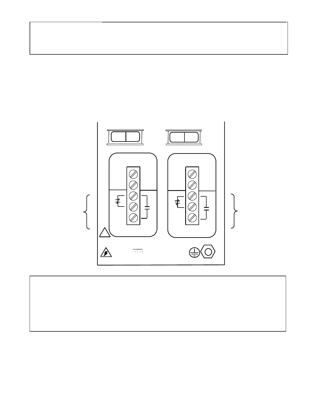
4.5.2 ALARM AND ALERT RELAY CONNECTIONS
The GARD 8000 chassis has two SPDT (Form C) relays mounted in the Power Supply I/O module.
The terminals are labeled as shown below. The Major Alarm relay terminals are on the left of the
figure and the Minor Alarm relay terminals are on the right of the figure. The contacts are rated
100mA, 300Vdc, resistive load.
38-150/200-300 VDC
3 AMPS 220 W MAX.
!
C
NC
NO
C
NC
NO
POWER SUPPLY 1
POWER SUPPLY 2
MAJOR
MINOR
SW1 SW2
1 0
1 0
WARNING
THE GARD 8000 CHASSIS MUST BE PROPERLY GROUNDED AS DESCRIBED
IN THE FOLLOWING PARAGRAPH BEFORE ATTEMPTING TO CONNECT
INPUT POWER. IMPROPER GROUND CONNECTIONS MAY RESULT IN
SYSTEM MALFUNCTIONS, EQUIPMENT DAMAGE, OR ELECTRICAL SHOCK.
4.5.3 CHASSIS GROUND CONNECTIONS
A protective earth stud at the lower right rear of the GARD 8000 chassis is the main ground for the
GARD 8000 terminal.