Current Differential Relay
GARD 8000 SYS RFL Electronics
June 20, 2014 13-76 973.334.3100
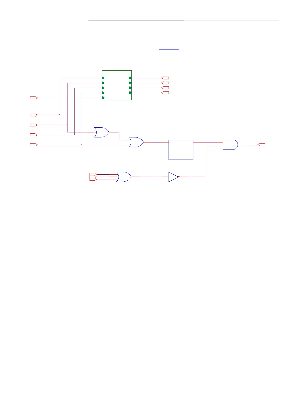
These individual trip signals are combined and fed into a timer which holds the output active for a
period after the trip stops being calculated. Following the trip timer the trip output will be blocked if
the relay is out of service, is in test mode (see section 13.5.2.1), or the relay is in major alarm (see
section 13.5.2.4).
Figure 13-49 Three Pole Tripping Logic
13.5.3.2 SINGLE POLE TRIPPING LOGIC
The single pole tripping logic is implemented in the GARD controller’s logic processing and is shown
in Figure 13-50. As with the three pole logic each of the phase and ground processing routines have
independent outputs to the logic bus. The generation of these per-phase trip signals is somewhat more
complicated than for the three phase relay. A single-pole relay may be configured to operate as with
single-pole, multiphase, or three-pole tripping.
As with the three pole logic the phase trip signals are latched and then routed to front panel LED
indicators. A target reset function is implemented using the front panel pushbutton.
Each phase has an independent trip output with a trip release timer which holds the output active for a
period after the trip stops being calculated. Depending upon configuration a phase may be forced to
trip even if no fault was calculated for that particular phase (as described below). Following the trip
timer each trip output will be blocked if the relay is out of service, is in startup mode, or the relay is in
major alarm.
If the relay is configured for 3-pole tripping only a trip on any phase or ground will force a 3-pole trip
(any of the trip outputs may be used). If the relay is operating in backup mode the logic will
automatically operate in 3-pole tripping mode regardless of the user selection.
If the user has enable the single-pole ground tripping feature a trip calculated by ground can cause all
three poles to trip. A trip calculated by ground is delayed to allow the trip to be cleared normally.
HMIIN1
HMIOUT12
PH_B_TRIP
HMIOUT10
OUT OF SERVICE
U26
PH_A_TRIP
U27
MAJOR ALARM
PH_G_TRIP
TRIP_OUT
U28
TIMER
ATT_DEC = 0_100
NUMBER = 3
OUTIN
HMIOUT13
PH_C_TRIP
STARTUP MODE
quad_latch_x
quad_latch_x
Input1
Input2
Input3
Input4
Reset
Output1
Output2
Output3
Output4
HMIOUT11