Power Line Carrier
GARD 8000 SYS RFL Electronics
April 23, 2015 10-15 973.334.3100
13. Verify a reflected power of 11% (See Table 10.5 for tolerance)
14. Remove the 25 ohm load, and reconnect the non-inductive nominal load.
15. Verify a reflected power of 0% (See Table 10.5 for tolerance)
16. Verify the accuracy of the Reflected Power meter with a non-ideal, non-inductive load. Check
each point on the following Table.
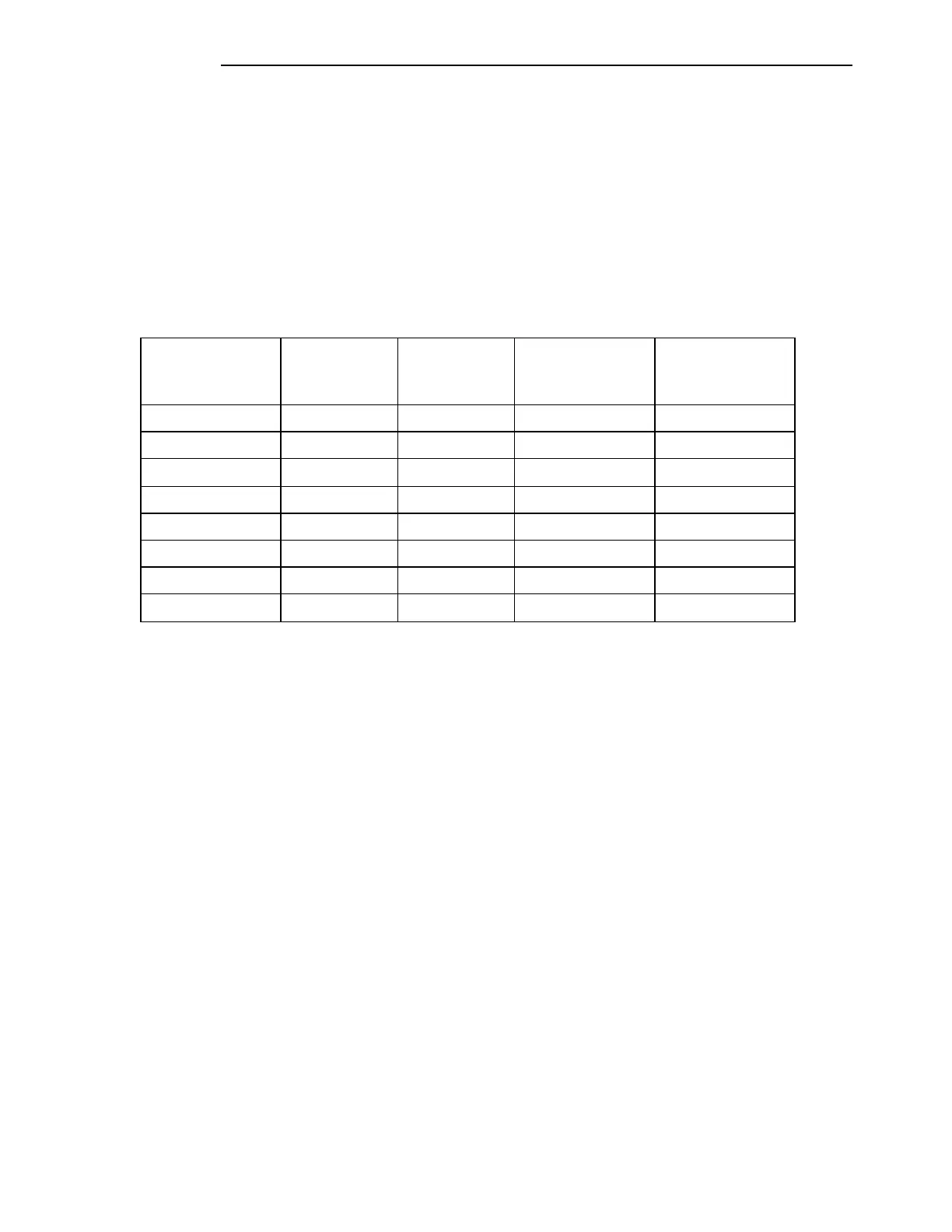
Table 10-8. Common RPM test values
Actual Line
Impedance
(Ohms)
Tolerance
Up to 200 KHz
(%)
Tolerance
Above 200 KHz
(%)
* The screen will indicate above 40% for these conditions.
Note that the RPM indication will not drift over time more than 1%, given constant line
conditions.
Tolerances measured at the GARD 8000 chassis connector. Adding Hybrids will degrade
accuracy.
10.7 CARRIER LEVEL INDICATOR
The GARD PLC has a carrier level indicator output for use with external measuring devices such as a
panel meter (see 10.7.1) or an analog RTU input. The value at this output represents a variance in
received signal level from the initial signal level when the unit was commissioned. The output is an
analog value that is at mid-scale when the commissioned level is being received. It is above mid-scale
for higher levels and below mid-scale for lower levels.
The output is actually a voltage output with one of three jumper selectable resistors in series with it.
When attached to the proper load, the current swings over the designated range.


 To Next Page