Chassis Configuration Settings
GARD 8000 SYS RFL Electronics
April 1, 2012 7-78 973.334.3100
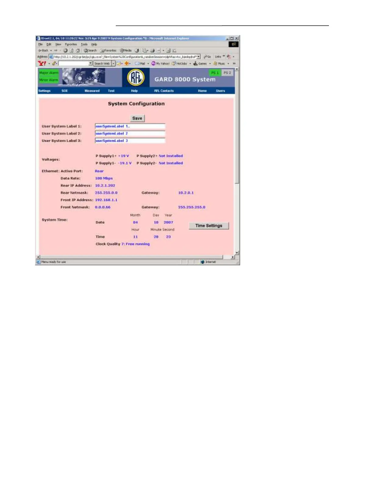
Figure 7-46. System Configuration web page
The user system labels provide text boxes for identifying the GARD 8000 chassis. Examples include
substation names, line numbers or other information that can be applied to the complete GARD 8000
system. Communications modules and I/O modules have additional label fields to further identify
specific functions within the GARD 8000 System.
User System Label 1 thru 3
Enter a descriptive name for System Label 1 thru 3.
Voltages
The GARD system can use either single or dual power supplies. A single power supply can be
connected to either the supply 1 or supply 2 positions. The voltages displayed are the output voltages
from the power supply to the chassis midplane.
Ethernet
Displays and Settings
Active Port
Displays which of the two Ethernet ports Front/Back are active.