System User Interface
GARD 8000 SYS RFL Electronics
August 1, 2012 5-5 973.334.3100
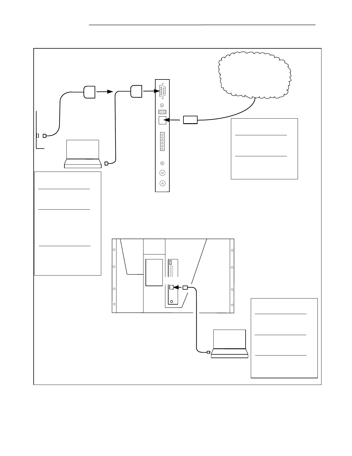
5.1.1 COMMUNICATION OVERVIEW
RJ-45
System I/O Module
on rear of GARD
RS-232
Front of GARD
Modem
DB-9 Male
DB-9 Female
DB-9 Female
DB-9 Female
RJ-45
RJ-45
Serial RS-232
Network Connection
GARD Factory Settings:
IP Address 192.168.1.1
Subnet 255.255.255.0
PC Settings:
IP Address 192.168.1.2
Subnet 255.255.255.0
Baud rate: 9600
Data 8; Parity 0; Stop Bits 1
Enable Hardware Flow Control
Cable for Modem Connection
9 Pin 'D' Straight Connection
May also be used to connect to
local PC using null modem
cable
Ethernet
Local User Interface
GARD Factory Settings:
IP Address 192.168.1.1
Subnet 255.255.255.0
PC Settings:
IP Address 192.168.1.10 (typ)
Subnet 255.255.255.0
Cable :
Cat5 Patch Lead
RJ-45 (Straight)
Ethernet
Remote Access User Interface
GARD Factory Settings:
IP Address - Not allocated
Subnet - Not allocated
Cable :
Cat5 Patch Lead
RJ-45 (Straight)
Figure 5-6. Communication Overview (Typical)