Chassis Configuration Settings
GARD 8000 SYS RFL Electronics
April 1, 2012 7-79 973.334.3100
Data Rate
Displays the current data rate of the Ethernet connection.
Rear IP address
Displays the current IP address for the rear Ethernet port.
For additional security the user must be connected to the front Ethernet port and have the proper
security access level authorization to change the address of the rear Ethernet port. When connected to
the front Ethernet port enter the desired address in the space provided and select SAVE from the top of
the page.
Rear Netmask
Indicates the subnet mask of the rear port. The administrator who assigns the IP address will also
assign the netmask values. In most cases the subnet mask will remain the same; 255.255.255.0
All systems on the same subnet must use the same subnet mask.
Gateway
Displays the gateway IP address for the corresponding fiber ethernet port.
Front IP address – Displays the IP address of the front Ethernet port. This address is programmed at
the factory and cannot be changed.
Front Netmask
Indicates the subnet mask of the front port. The administrator who assigns the IP address will also
assign the netmask values. In most cases the subnet mask will remain the same; 255.255.255.0
All systems on the same subnet must use the same subnet mask.
System Time
Displays the current date and time if an external clock source is being utilized. If an external clock
source is not being utilized the date and time may be set on the “Time Settings Page” that follows.
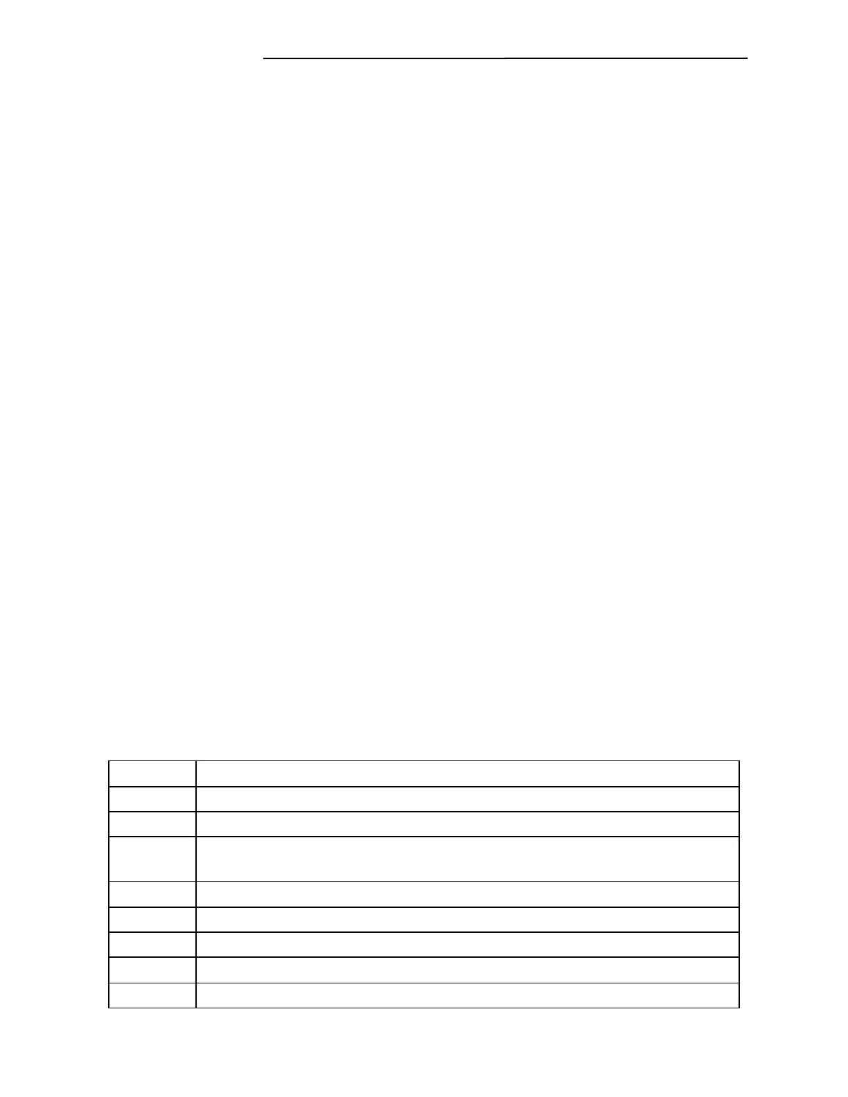
Clock Quality
For external time source only. This is a level indicator, zero being the most accurate and 7 the least
accurate.
Table 7-6. Clock Quality Level Indication
The interface is receiving time from GPS and the 1 pps signal is locked.
The interface is receiving time from IRIG-B and the 1 pps signal is locked.
A GPS has been sensed and the 1 pps is locked, however the GPS is indicating
poor health, i.e. not enough good satellite data.
A GPS has been sensed, but is reporting poor health with no 1 pps signal lock.
The interface is receiving time from IRIG-B, but there is no 1 pps signal lock.
The GPS is reporting good health, but there is no 1 pps signal lock.
The clock is free running.
 Loading...