Power Line Carrier
GARD 8000 SYS RFL Electronics
April 23, 2015 10-25 973.334.3100
10.8.5 LINE BOARD
The RFL 9508 Line Board serves as the connection point between the RFL 9508 RF Chassis and the
Line Coupling equipment. Because it contains no active components, the Line Board does not require
any dc input voltage.
100
P
200
P
300
P
410
P
.001U
F
.002U
F
12.1 1/
2W
12
2.5W
12
2.5W
50
2.5W
50
5W
.003U
F
.0041U
F
.01U
F
56UH
9.5
A
100UH
9.5
A
180UH
9.5
A
12.1 1/
2W
12.1 1/
2W
8-
18UH
10UH
9.5
A
18UH
9.5
A
33UH
9.5
A
55869
55869
55689
55688
FUSE 2A
250V
FUSEHOLDE
R
32882
FUSEHOLDE
R
32882
FUSE 2A
250V
12
1
47.
5
4733A
4733A
43.
2
ARRESTO
R
92627
99134
180U
H
92627
ARRESTO
R
PART
NUMBER
SERIAL
NUMBER
130/
150
130/
150
G
TP8
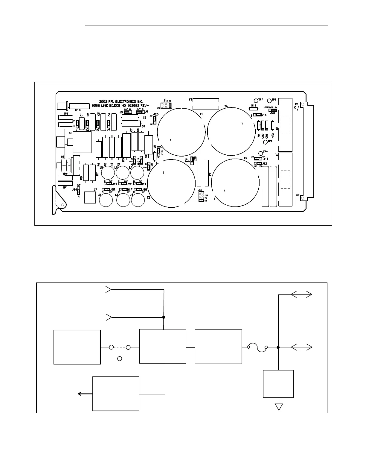
Figure 10-16. Line Board
10.8.5.1 THEORY OF OPERATION
The RF Line board connects the RFL 9508 to the line coupling equipment. It contains two hybrid
transformers, a receive attenuator, a complex balance network, two impedance matching transformers,
and two surge arrestors. A block diagram of the Line Board appears below.
Figure 10-17. Block Diagram, RFL 9508 Line Board
From Power Amp 1
Line Coupling
Equipment
Balance
Transformers
Matching
Attenuator
Arrestors
Receive
Output
To
Rx Filter
From Power Amp 2
(when used)