Power Line Carrier
GARD 8000 SYS RFL Electronics
April 23, 2015 10-44 973.334.3100
10.8.13.5 ATTENUATOR BOARD SETTINGS
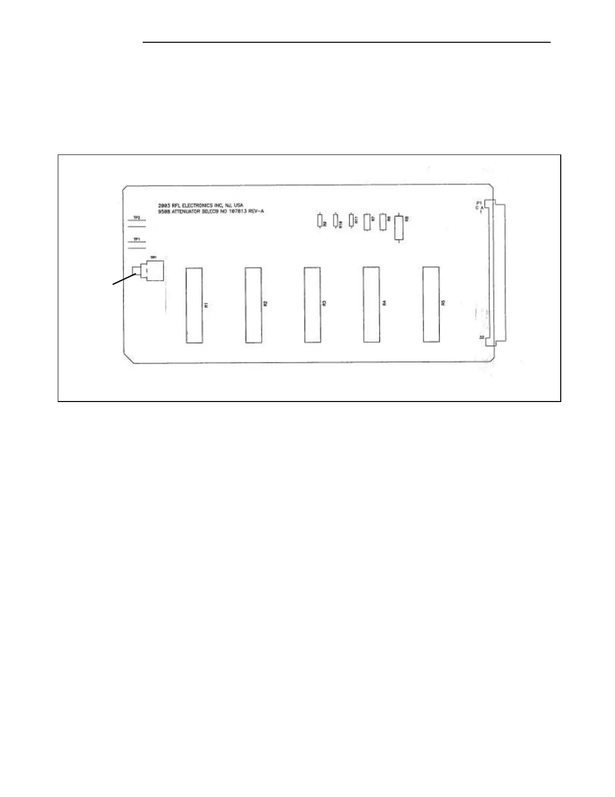
The Attenuator Board has one toggle switch (SW1) that must be set for proper system operation. The
toggle switch SW1 selects either Normal or Loopback operation. In Normal operation, set the switch to
the UP position. In Loopback operation set to switch to the DOWN position. The switch location is
shown below, and is accessible when the Attenuator Board is plugged into the chassis.
Figure 10-31. Attenuator Board, Location of SW1
10.8.13.6 SETTING JUMPERS ON THE RX FILTER AND RX FILTER TUNING
The Rx Filter has a large number of jumpers (about 100) that must be configured for proper system
operation. These jumpers allow a user to select the bandwidth, which can be either 8kHz or 16kHz, and
to tune the center frequency, which can be from 24kHz to 496kHz (the outer edges are 20kHz and
500kHz). The location of these jumpers is shown in Figure 10-31. Tuning the filter is done per the
Microsoft Excel® Worksheet “9508 RX Filter Programming Sheet.xls” available on request from
RFL.
In addition to the jumpers, the Rx filter has three tunable inductors, L1, L2 and L3. Their functions are
as follows:
L2 controls the balance of the filter (flat response at both sides of center frequency).
L1 controls the attenuation at the upper side of center frequency.
L3 controls the attenuation at the lower side of center frequency.