Ethernet TPS Module
GARD 8000 SYS RFL Electronics
April 14, 2015 14-11 973.334.3100
Once a file has been uploaded the “Config” button for that client will be enabled and should be yellow.
This indicates that the CID file is uploaded but the Logic Bus Bits have not been configured. Clicking
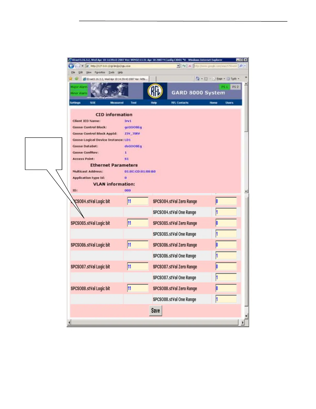
on the “Config” button will bring up the web page shown on the next page.
Figure 14-10 Ethernet TPS Module, Logic bit Configuration
This top portion of the above web page will display user information while the bottom portion under
“Ethernet TPS” will allow the user to configure the Logic Bus Bits. The incoming GOOSE message
has variables that can be mapped to a logic bit using the following settings.
Logic Bit
From the file
specified on
the previous
web page.