Chassis Configuration Settings
GARD 8000 SYS RFL Electronics
April 1, 2012 7-10 973.334.3100
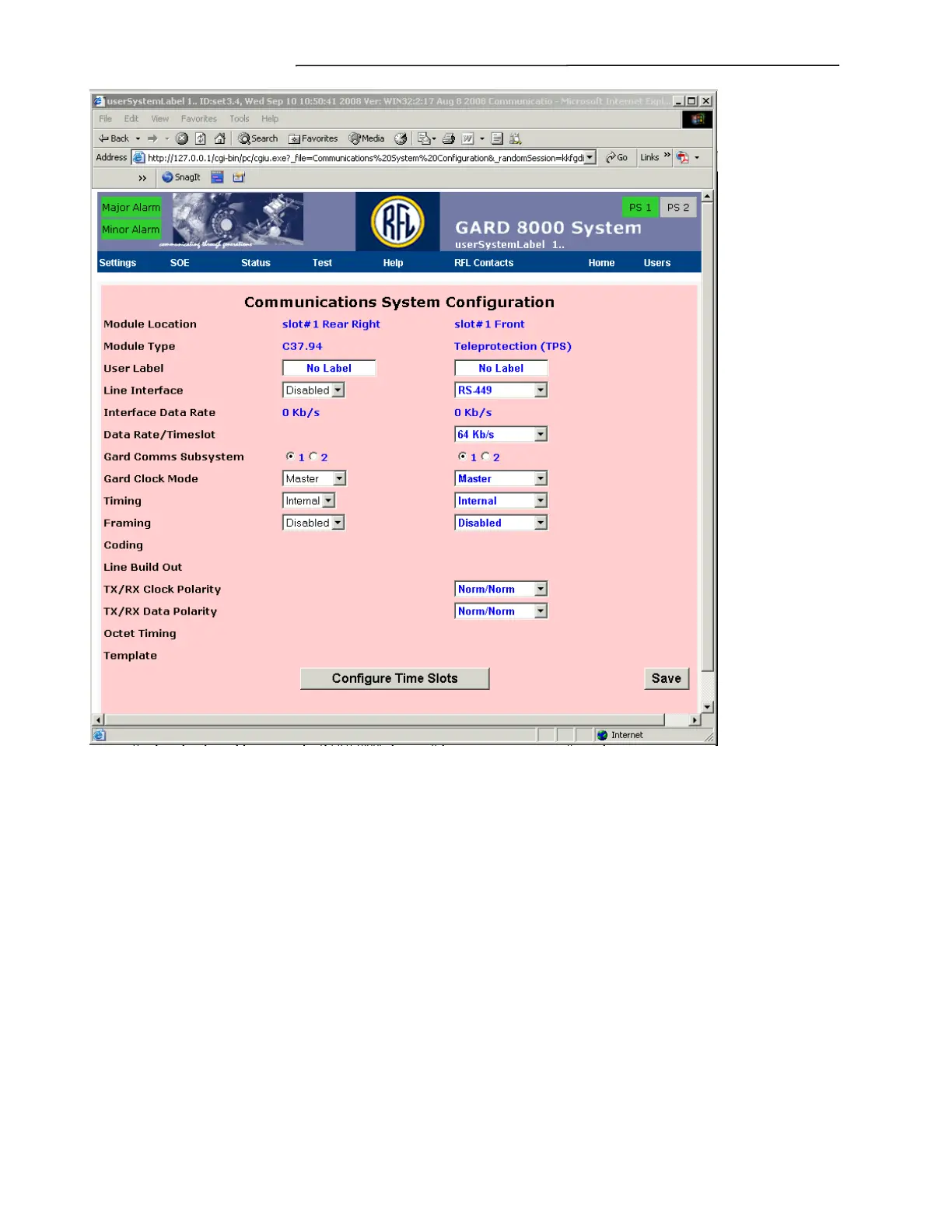
Figure 7-7. Communications System Configuration web page
Note: The Communications System Configuration displays the configuration of all
communications I/O modules in a GARD 8000 system. Figure 7-7 only refers to the Digital
Interface Module configuration in this example. Some parameters may not apply to all
modules. Those parameters that do not apply to a particular module will be blank on the above
web page but are described below.
Module Location
Displays the physical location in the GARD 8000 chassis of the communications interface to be
configured.
Module Type
Displays the type of communications interface to be configured.
User Label
Enter in a descriptive name for the communications interface.
Line Interface