Installation and Commissioning
GARD 8000 SYS RFL Electronics
November 28, 2017 4-32 973.334.3100
PS 48/
125V
Single Main Controller (Slot 2)
Single Power Supply
Normal
Disable
DS-1
DS-2
DS-4
DS-3
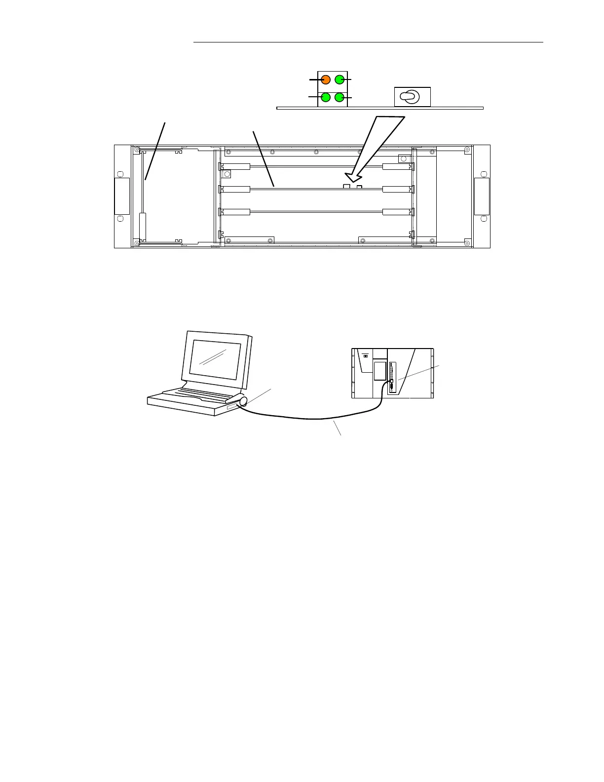
Figure 4-15. GARD 8000 Controller Module (Audio-Tone Commissioning)
4.6.2.2 FRONT PORT ETHERNET CONNECTION
GARD8000
Laptop/Notebook PC
Standard Cat 5 Patch Cable
IP Address: 192.168.1.10
Subnet Mask: 255.255.255.0
IP Address: 192.168.1.1
Subnet Mask: 255.255.255.0
RJ-45 Ethernet Port
RJ-45 Ethernet Port
Note: The GARD 8000 is delivered with pre-set IP addresses. The front port IP address is factory set
to 192.168.1.1 with a subnet mask of 255.255.255.0. The Rear port IP address is configurable. The
factory set rear port IP address is provided on a removable sticker on the System I/O module, and is
also specified in the order packing sheet for the GARD 8000 System.
The IP Address assigned to the front port is 192.168.1.1 for every GARD 8000 chassis.
DO NOT plug this port into a LAN. You cannot have more than one device with the same
address on a network. The front port is strictly for direct connection to a Laptop PC. The
Laptop should have an IP Address on the same subnet (192.168.1) as described below. The front
port has no default gateway configured, so it is not routable. This is done for security purposes.
1. Connect a standard Cat 5 Patch Cable from the RJ-45 Ethernet port on your PC to the front
RJ-45 Ethernet port on the GARD 8000.
2. Configure the IP address of your PC as follows:
a. From a PC desktop, click Start, click Run, type ncpa.cpl, and then click OK.
b. A Network and Dial Up Connection window will appear.