Module Descriptions
GARD 8000 SYS RFL Electronics
April 23, 2015 6-20 973.334.3100
Note: The following table lists test points designed for factory use only. These points are not ESD
protected. Users should not need to connect test equipment to these points in the field.
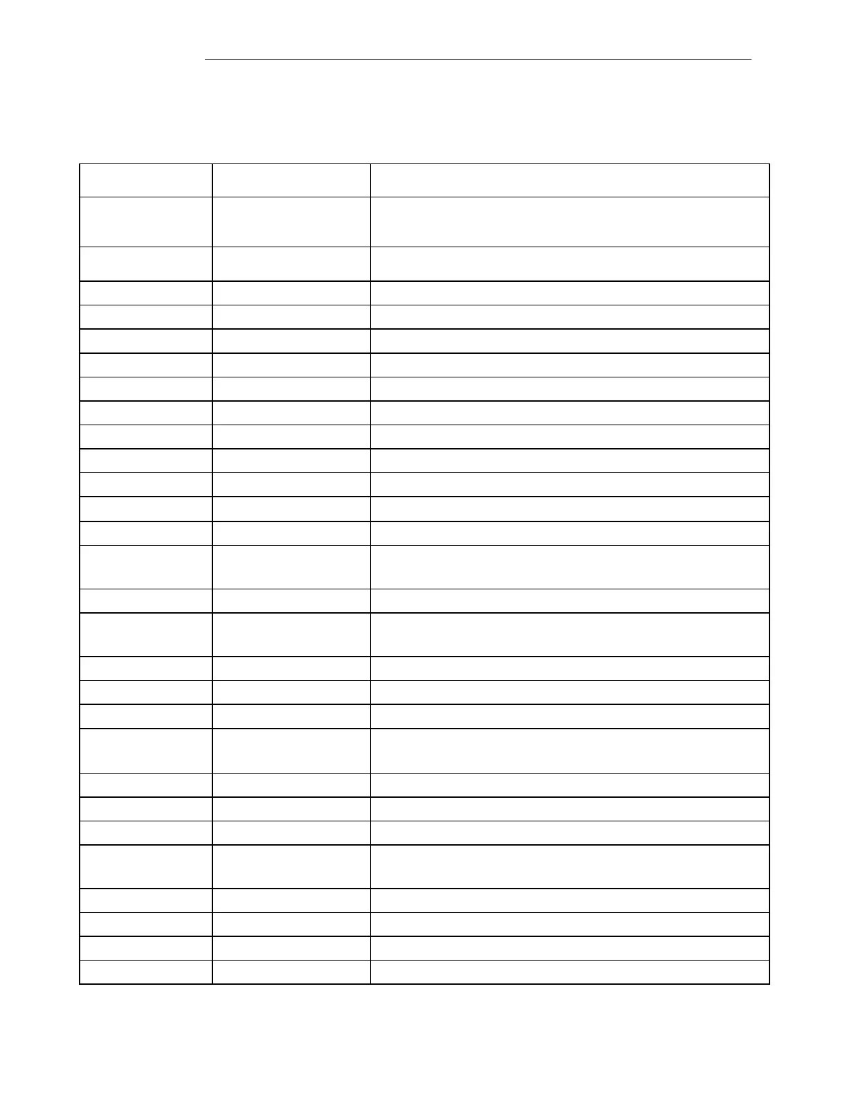
Table 6-10. Jumper Settings and Switch Function for the GARD 8000 PLC Digital Module.
Green = Enabled
Amber = Disabled
Red = Tx Disabled
Green = No Alarms
Red = Any Alarm(s)
Debug Header: For factory use only.
PIC Programming Header: For factory use only.
Actel Programming Header: For factory use only.
NORM: Must always be in NORM position
TEST: For factory use only.
NORM: Must always be in NORM position
DEBUG: For factory use only.
Flash Programming Header: For factory use only.
DSP: For factory use only.
MPU: For factory use only.
NORM: Must always be in NORM position
PRGM: For factory use only.
Line Out: In 4W Mode: Tx output to line
In 2W Mode: Tx/Rx line connection
+2.5V: +2.5V Digital supply