Applications
GARD 8000 SYS RFL Electronics
February 14, 2011 2-9 973.334.3100
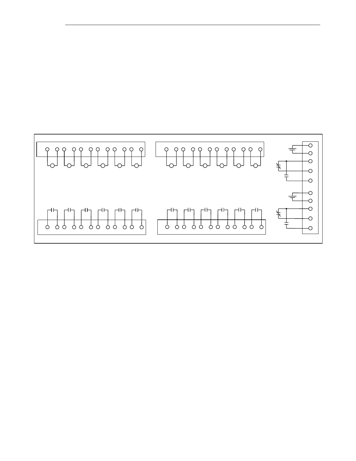
External connections are made as shown in the following dc schematic for the example system
configuration.
125 46 39 8 712 11 10
12 11 10 9 8 7 6 5 4 3 2 1
131516 141719 18202124 23 22
131516 141719 18202124 23 22
In 12 In 11 In 10 In 9 In 8 In 7
Out 12 Out 11 Out 10
Out 9 Out 8
Out 7
In 6 In 5 In 4 In 3 In 2 In 1
Out 6 Out 5 Out 4 Out 3 Out 2 Out 1
Slot 2
Slot 2
Slot 4 Slot 4
PS 1
PS 2
+
-
+
-
+
-
+
-
Programmable Inputs and Outputs
Major
Alarm
Minor
Alarm
Figure 2-6. GARD 8000 DC Connection diagram, 3U Distance Relay Plus Teleprotection System