Installation and Commissioning
GARD 8000 SYS RFL Electronics
November 28, 2017 4-11 973.334.3100
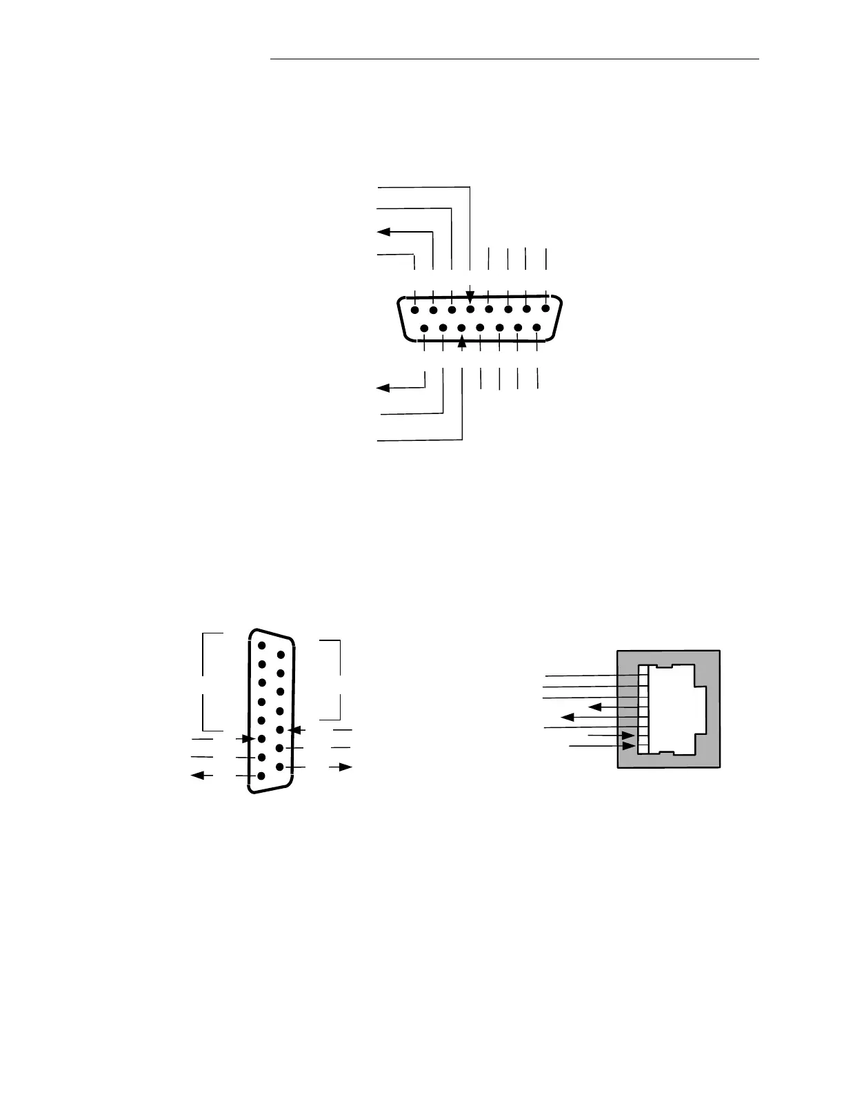
4.5.7.2 G.703 CONNECTIONS
A G.703 Interface may be used on the Power Supply I/O in place of the Multi-protocol Interface. The
G.703 Interface uses a DB-15 male connection. The pin-outs are shown below.
1 2
4
3 5 6 7 8
9 12 1310 11 14 15
Chassis GND
SD(A)
Not Used
RD(A)
Not Used
SD(B)
Not Used
RD(B)
Not Used
Figure 4-6. Pin-Outs G.703
4.5.7.3 T1/E1 INTERFACE CONNECTIONS
The pin-outs for the T1/E1 Interface Module are shown below. The user can choose between a DB-15
male connection and an RJ-48C connector.
1
4
5
6
7
2
Not Used
SD -
3
RD -
8
Not Used
9
SD +
10
Not Used
11
RD +
12
13
14
15
Not Used
RJ-48C
1
2
3
4
5
6
7
8
DB-15 Male
RD -
RD +
Not Used
SD -
SD +
Not Used
Chassis GND
Figure 4-7. Pin-Outs, T1/E1