System User Interface
GARD 8000 SYS RFL Electronics
August 1, 2012 5-21 973.334.3100
The TSD can Wake-Up to a designated screen. With a Laptop or PC connected to the GARD chassis
select ‘Settings’ > ‘Chassis Configuration’ and select the Controller Module to access the System
Configuration web page. A designated HMIOUT bit can be set high to display the required screen;
bits 0 – 63 are available. Set the bit and then select the screen to display before clicking “Save.”
5.5.5 TSD SITE MAP
The following sub-section will show some typical status screens available through the main TSD
menu. Each customer’s unique chassis configuration is read into the TSD Measured Values page. If
the inventory is changed the TSD display will adjust accordingly. The TSD display can be customized
as required.
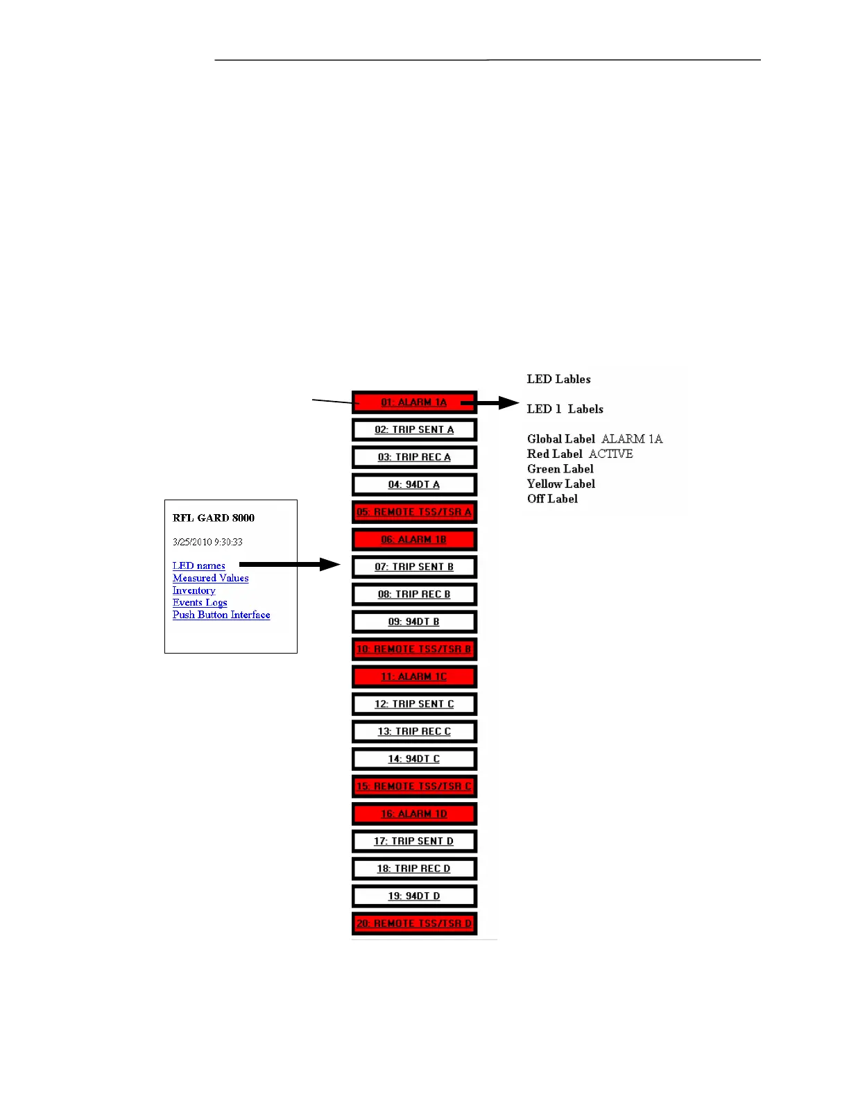
LED Names: This TSD page will show the LED assignments on the Front Panel Display Unit of the
GARD, label information and LED color assignments are shown. There are an additional 20 virtual
LED’s available (not shown). Following is a typical GARD 8000 “LED Names” display. For LED
Logic Assignment Configuration see section 7.3.2.
Clicking the button
will give a discription
of the LED's logic
assignments
Figure 5-15. TSD LED Labels.
Measured Values: In the following example the “System Values” are displayed. This gives the user
an overall picture of his GARD system; individual modules will display information unique to that