Module Descriptions
GARD 8000 SYS RFL Electronics
April 23, 2015 6-26 973.334.3100
6.6 SYSTEM I/O MODULES
The function of the System I/O Module is to provide the physical connection point between the GARD
8000 and the substation network. In addition to this, the System I/O Module provides the following
three timing functions:
Optional GPS
IRIG-B
1PPS (1 pulse per second timing signal)
An Optional GPS interface module (GPS time receiver) can be installed in the System I/O Module.
When it is installed, (the location is indicated by the dashed lines in Figure 6-13 for the 6U module and
Figure 6-15 for the 3U module), a GPS antenna must be connected to the SMA series connector
labeled “GPS” at the rear of the System I/O Module. When the GPS option is installed, the BNC
connectors labeled “IRIG-B’ and “1PPS” function as outputs and can be used to drive equipment
external to the GARD 8000. In this case the IRIG-B output is unmodulated.
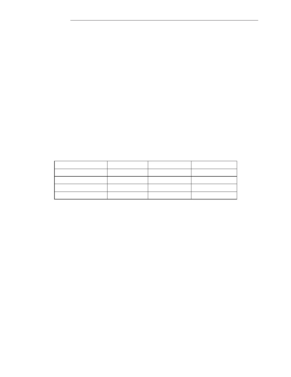
There are 4 different System I/O Modules available, they are listed below.
Table 6-12 System I/O Modules
If the Optional GPS interface is not installed in the System I/O Module several jumpers must be
installed on the System I/O Module as indicated in Table 6-12. When the optional module is not
installed, the BNC connectors labeled “IRIG-B” and “1PPS” function as receive input signals from
IRIG-B equipment external to the GARD 8000. The IRIG-B input signal can be modulated or
unmodulated. A Jumper on the System I/O Module must be set by the user to indicate if the input
signal is modulated or unmodulated.
There may be a situation where the customer requires an IRIG-B signal accessed through the rear
RS-232 port, when this is required jumpers J3 and J12 must be set to the IRIG-B position on the
System I/O Module.
The 6-pin terminal block at the rear of the System I/O module is for the MODBUS or DNP protocol.
The 6-pin connector is always installed, but the software is optional.
The 3U System I/O Module is electrically identical to the 6U System I/O Module except that it is in a
different package.